ORDER NO.
PIONEER CORPORATION 4-1, Meguro 1-chome, Meguro-ku, Tokyo 153-8654, Japan
PIONEER ELECTRONICS (USA) INC. P.O. Box 1760, Long Beach, CA 90801-1760, U.S.A.
PIONEER EUROPE NV Haven 1087, Keetberglaan 1, 9120 Melsele, Belgium
PIONEER ELECTRONICS ASIACENTRE PTE. LTD. 253 Alexandra Road, #04-01, Singapore 159936
PIONEER CORPORATION 2005
RRV3204
T ZZK JUNE 2005 Printed in Japan
FOR PRECAUTION OF
REASSEMBLY AND DISASSEMBLY
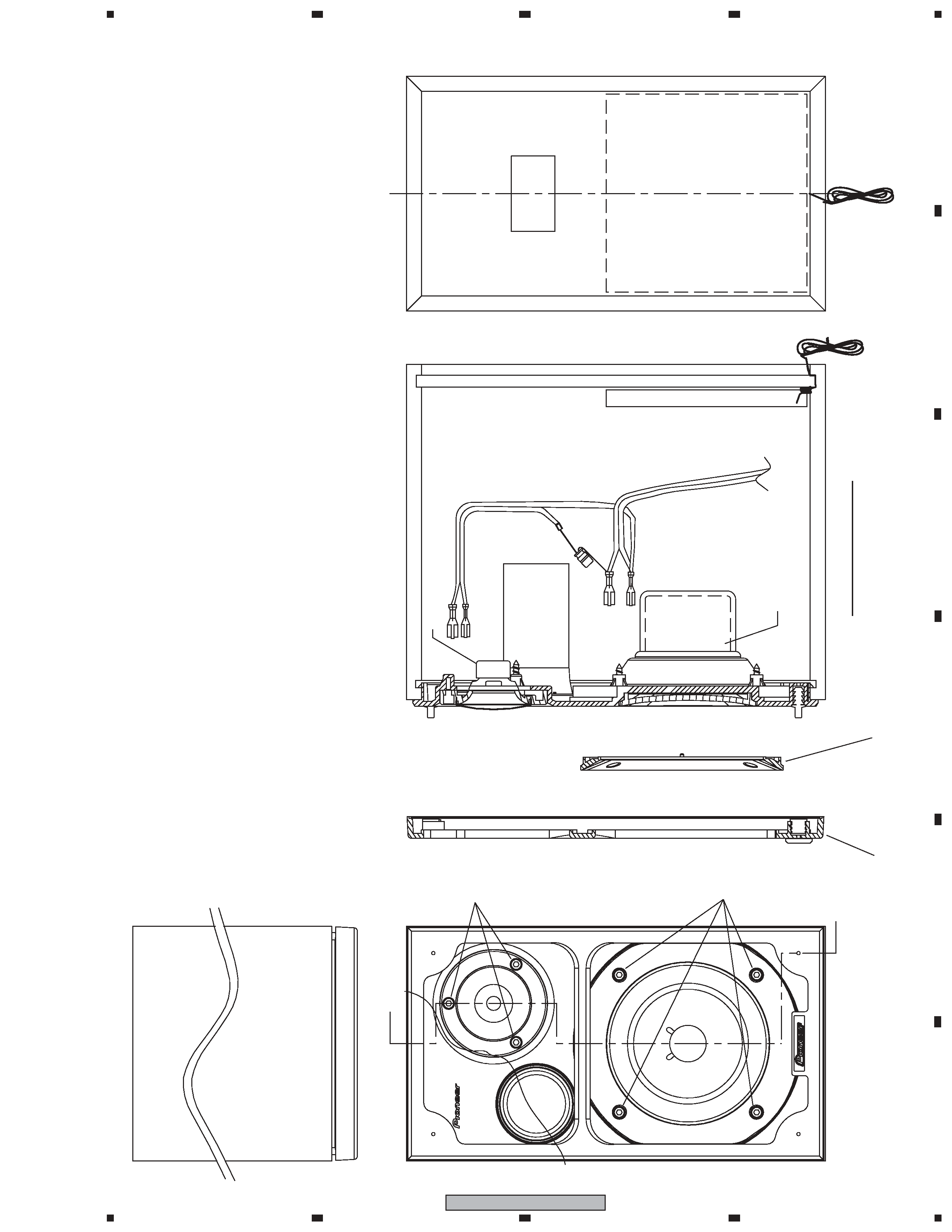
The grille is attached to the cabinet by catches. Detach by pull-
ing it toward you.
The woofer, together with the flange, is atached to the baffle by
4 external screws. To detach it, unfasten those screws. When
attachlng it, first fit the hole of the woofer into the threaded
screw hole on the baffle and face its terminal upward. Next fit
the boss of the flange into the hollow on the baffle.
The tweeter is atached to the baffle by 3 external screws. To
detach it, unfasten those screws. When attachlng it, fit the boss
of the tweeter into the hollow on the baffle and fit the hole of
the tweeter into the threaded screw hole on the baffle.
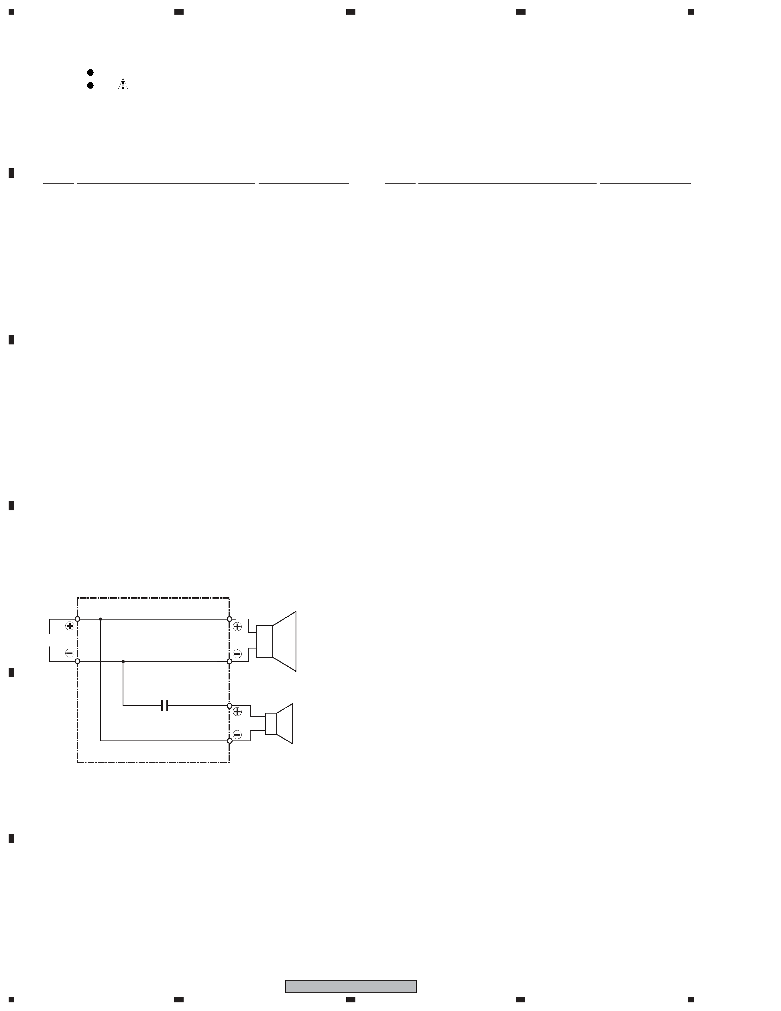
SPEAKER SYSTEM
S-HA5
XJC/E