ORDER NO.
PIONEER CORPORATION 4-1, Meguro 1-chome, Meguro-ku, Tokyo 153-8654, Japan
PIONEER ELECTRONICS (USA) INC. P.O. Box 1760, Long Beach, CA 90801-1760, U.S.A.
PIONEER EUROPE NV Haven 1087, Keetberglaan 1, 9120 Melsele, Belgium
PIONEER ELECTRONICS ASIACENTRE PTE. LTD. 253 Alexandra Road, #04-01, Singapore 159936
PIONEER CORPORATION 2004
RRV3030
T ZZM OCT. 2004 Printed in Japan
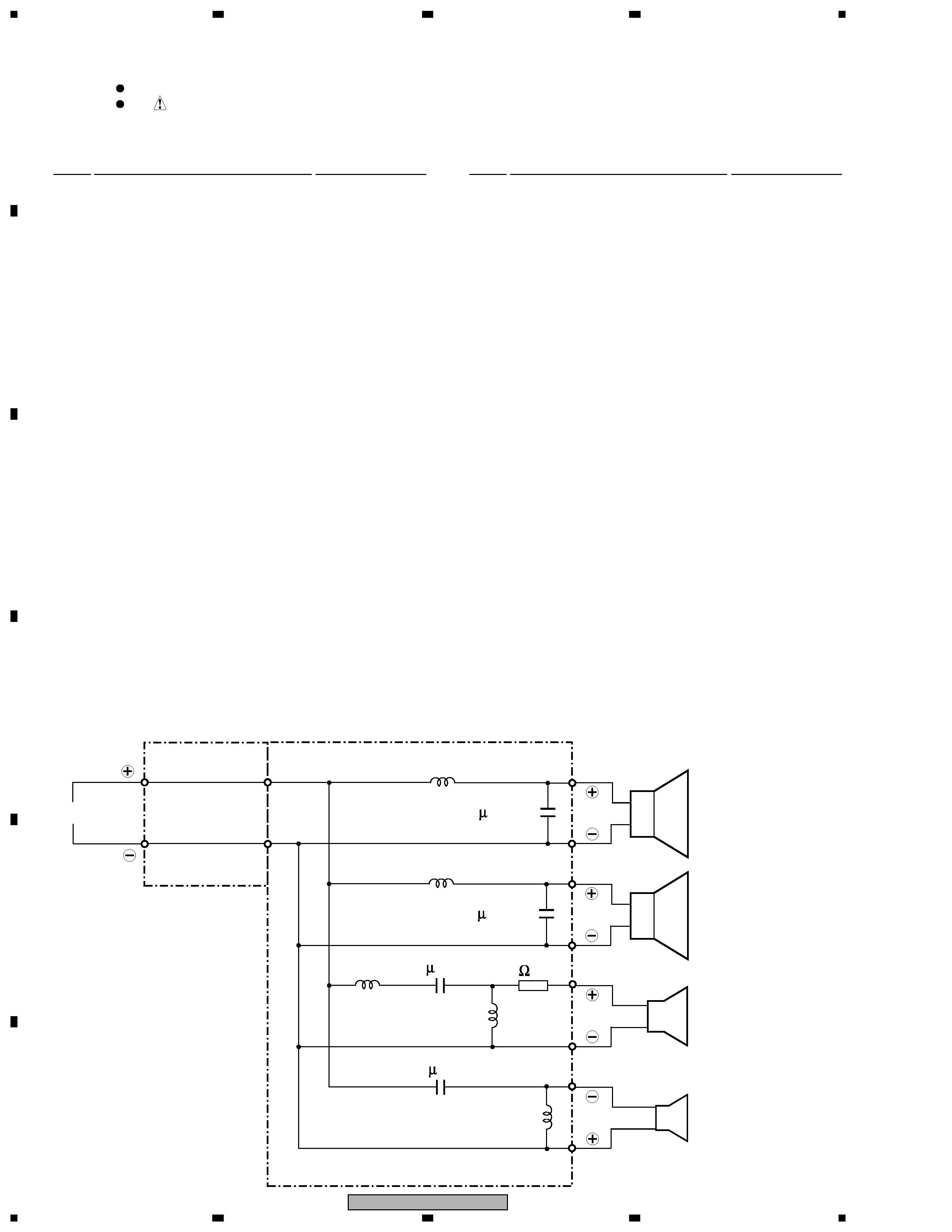
SPEAKER SYSTEM
FOR PRECAUTION OF
REASSEMBLY AND DISASSEMBLY
The grilles are attached to the cabinet by catches. Detach
them by pulling them toward you.
Woofers, Tweeter and Super-Tweeter are attached to the
baffle board by 15 external screws. To detach them,
unfasten those screws.
The baffle board is attached to the cabinet by 16 external
screws. To detach it, unfasten those screws.
The centre cosmetic flange is attached to the baffle board
by 4 internal screws. To detach it, unfasten those screws.
The network is attached to the baffle board by 5 internal
screws. To detach it, unfasten those screws.
S-H710V
XCN
S-H710V-2 XCN
S-H710V