ORDER NO.
PIONEER CORPORATION 4-1, Meguro 1-chome, Meguro-ku, Tokyo 153-8654, Japan
PIONEER ELECTRONICS (USA) INC. P.O. Box 1760, Long Beach, CA 90801-1760, U.S.A.
PIONEER EUROPE NV Haven 1087, Keetberglaan 1, 9120 Melsele, Belgium
PIONEER ELECTRONICS ASIACENTRE PTE. LTD. 253 Alexandra Road, #04-01, Singapore 159936
PIONEER CORPORATION 2005
RRV3267
T ZZK SEPT. 2005 Printed in Japan
SPEAKER SYSTEM
S-GX3V
XJM/E
FOR PRECAUTION OF
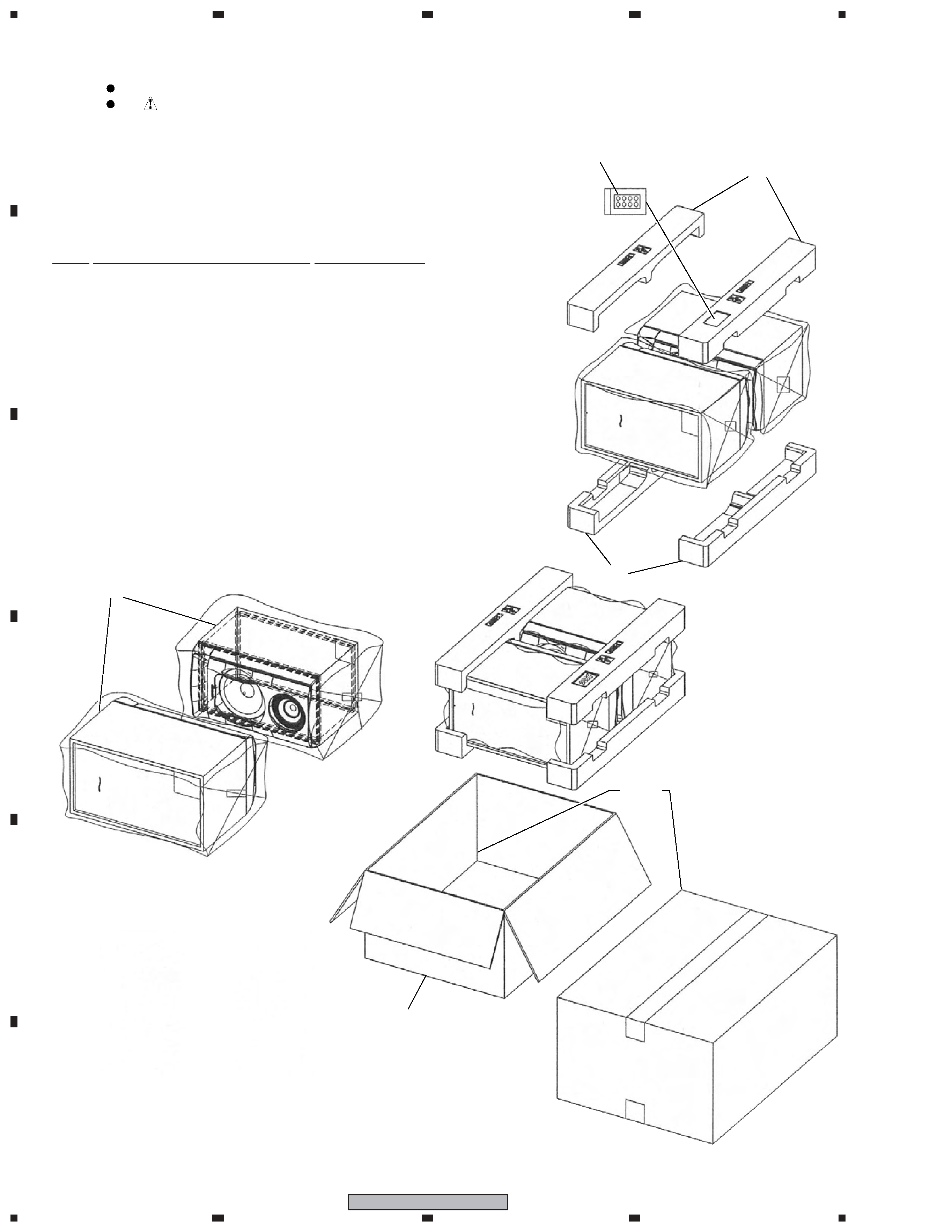
REASSEMBLY AND DISASSEMBLY
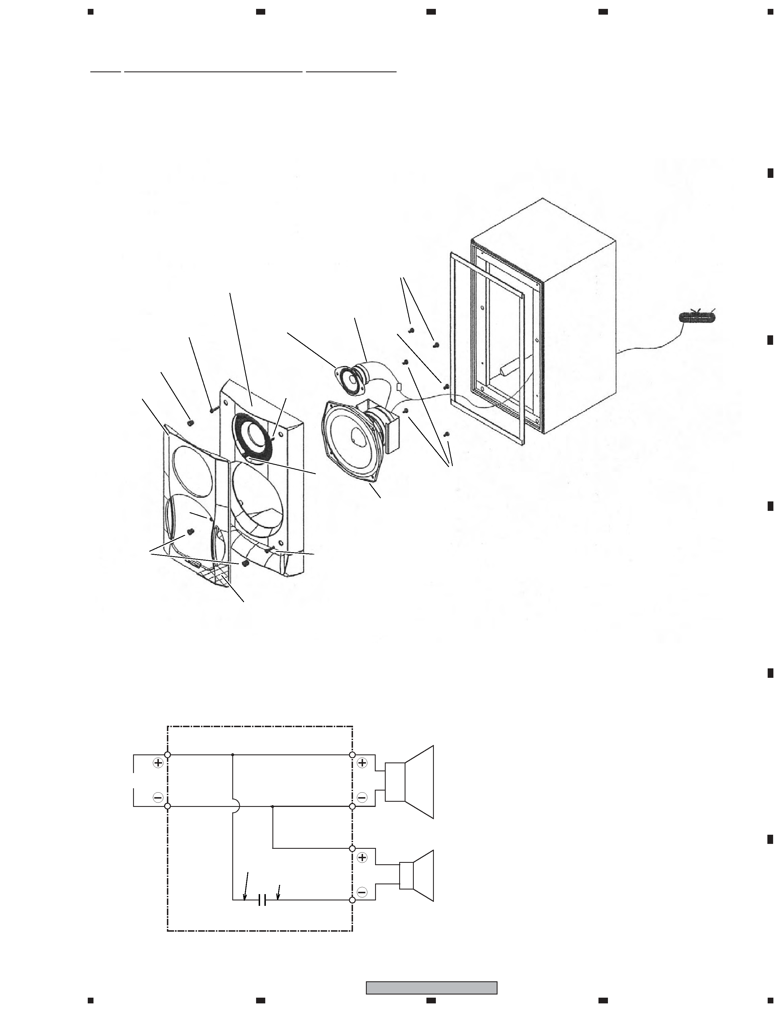
The grille assy is attached to the cabinet by catches. Detach by
pulling it toward you.
The catch is attached to the cosmetic baffle by press-fitting. To
detach it, insert a sharp-pointed tool like an eyeleteer into each
of side. To attach it, insert the holes of the cosmetic baffle assy
by press-fitting.
The cosmetic baffle is attached to the baffle by 4 external
screws. To detach it, first remove catches. Then unfasten those
screws.
The woofer is attached to the cosmetic baffle by 4 internal
screws. To detach it, first remove the cosmetic baffle. Then un-
fasten those screws. When attaching it, face its terminal down-
ward.
The tweeter is attached to the cosmetic baffle by 2 internal
screws. To detach it, first remove the cosmetic baffle. Then un-
fasten those screws. When attaching it, face its terminal down-
ward.