ORDER NO.
PIONEER CORPORATION 4-1, Meguro 1-chome, Meguro-ku, Tokyo 153-8654, Japan
PIONEER ELECTRONICS (USA) INC. P.O. Box 1760, Long Beach, CA 90801-1760, U.S.A.
PIONEER EUROPE NV Haven 1087, Keetberglaan 1, 9120 Melsele, Belgium
PIONEER ELECTRONICS ASIACENTRE PTE. LTD. 253 Alexandra Road, #04-01, Singapore 159936
PIONEER CORPORATION 2005
RRV3112
T ZZR FEB. 2005 Printed in Japan
S-FCRW4500
XTW/UC
SPEAKER SYSTEM
FOR PRECAUTION OF
REASSEMBLY AND DISASSEMBLY
CS Assy ( Subwoofer )
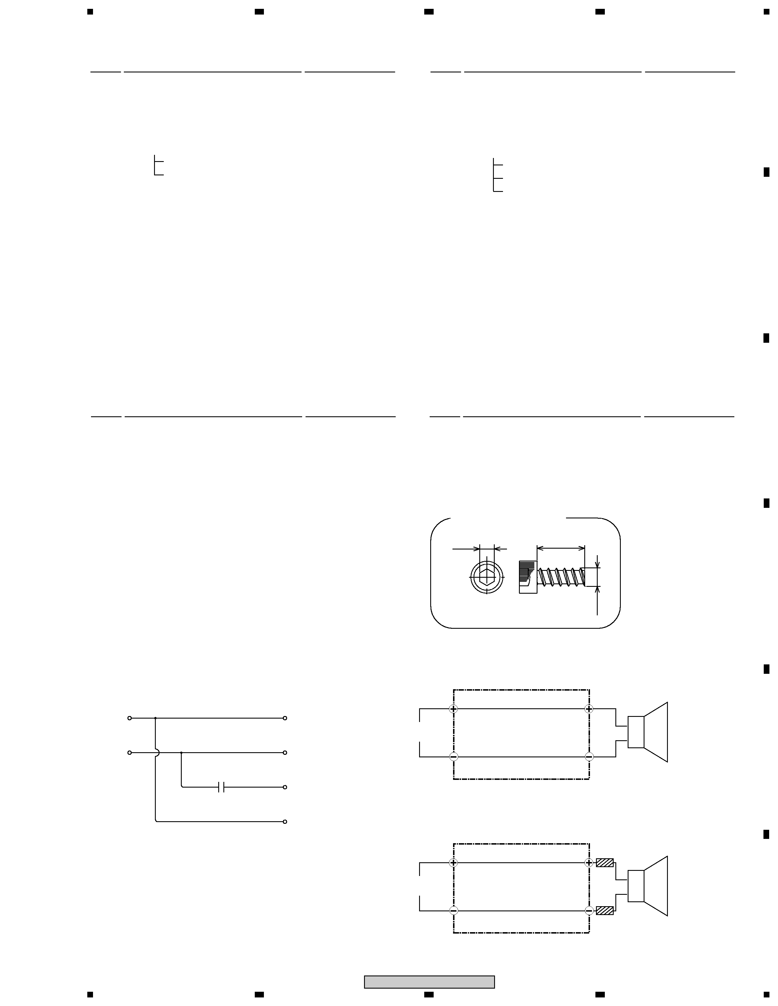
The subwoofer is attached to the baffle by 4 external screws.
To detach it, unfasten those screws. When attaching it, face its
terminal rightward.
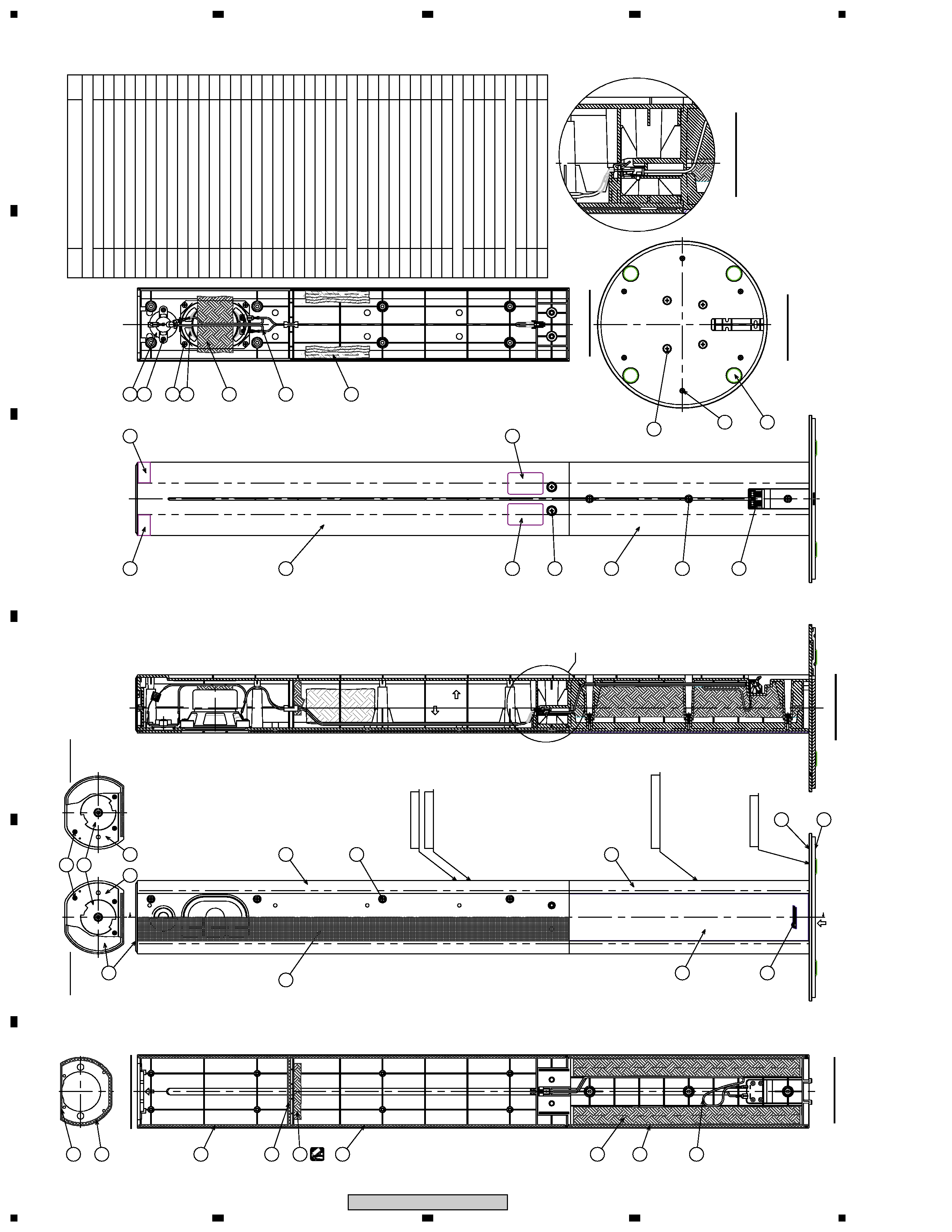
CS Assy ( Front Speaker )
The grille assy is attached to the cabinet by press-fitting. To
detach it, remove the top board by inserting a flat blade screw-
driver into the cabinet upper side. Then pry it open by inserting
a flat blade screwdriver between the grille and the cabinet.
The speaker unit is atached to the cabinet by 4 internal screws.
To detach it, first two screws of a connection part with a SP
stand are removed. Next the screw of a front cabinet is removed
and the hexagon socket screw of a top plate is removed. And
the screw which is fixing the SP unit is removed and a cable is
removed.
When attaching it, face its terminal toward the input terminal.
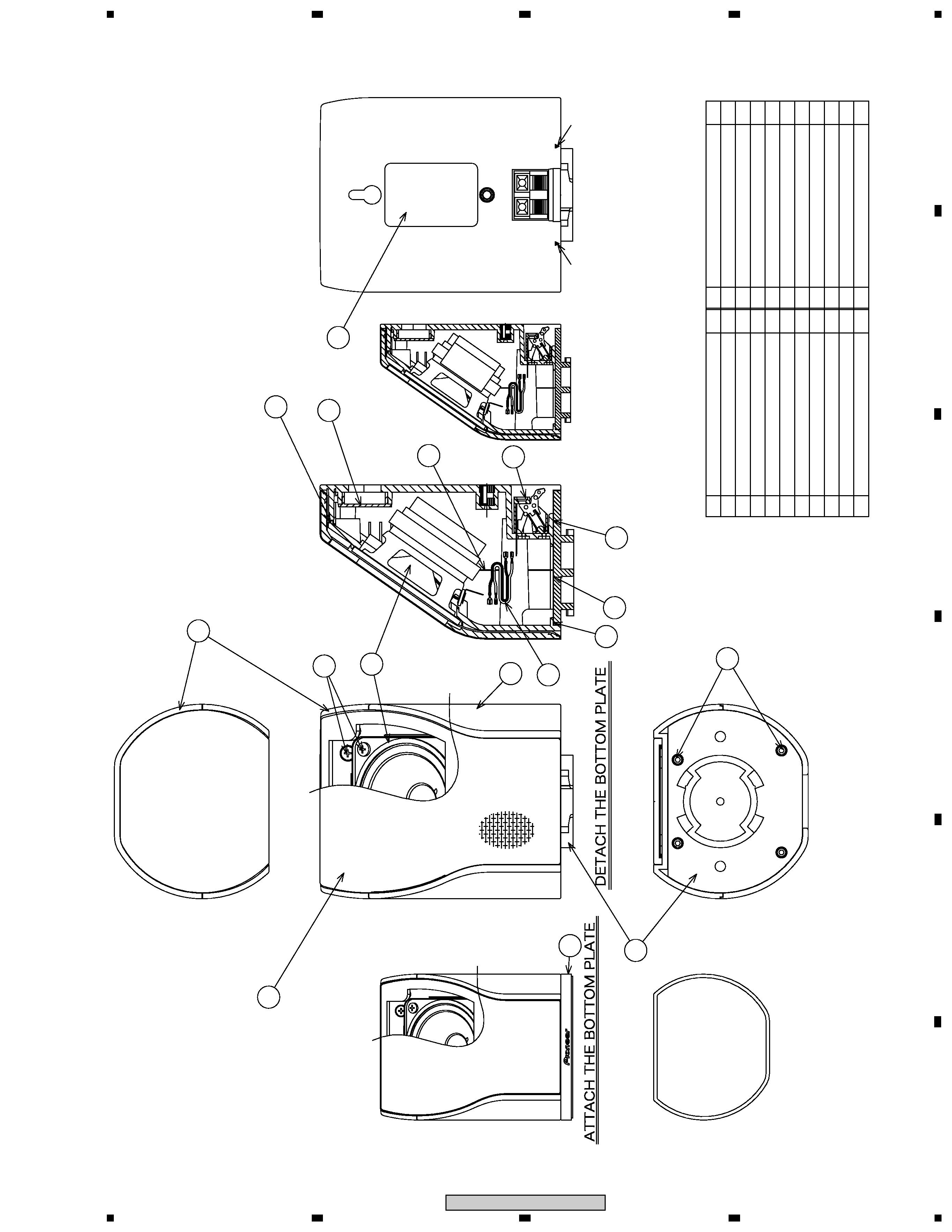
CS Assy ( Surround Speaker )
The grille assy is attached to the cabinet by its bosses. To de-
tach it, remove the stand by inserting a flat blade screwdriver
into the cabinet lower side. Then pry it open by inserting a flat
blade screwdriver into the grille slot.
The speaker unit is attached to the grille by 4 external screws.
To detach it, first remove the rear cabinet Then remove the
cable. When attaching it, face its terminal downward.
CS Assy ( Center Speaker )
The grille assy is attached to the cabinet by its bosses. To de-
tach it, remove the top board by inserting a flat blade screw-
driver into the cabinet upper side. Then pry it open by inserting
a flat blade screwdriver between the grille and the cabinet.
The speaker unit is attached to the cabinet by 4 internal screws.
To detach it, first unfasten screws of the bottom stand. Next
remove screws for the cabinet and SP unit. Then remove the
cable. When attaching it, face its terminal toward the input ter-
minal.
Front
Sub Woofer
Surround
Center