ORDER NO.
PIONEER CORPORATION 4-1, Meguro 1-chome, Meguro-ku, Tokyo 153-8654, Japan
PIONEER ELECTRONICS (USA) INC. P.O. Box 1760, Long Beach, CA 90801-1760, U.S.A.
PIONEER EUROPE NV Haven 1087, Keetberglaan 1, 9120 Melsele, Belgium
PIONEER ELECTRONICS ASIACENTRE PTE. LTD. 253 Alexandra Road, #04-01, Singapore 159936
PIONEER CORPORATION 2005
RRV3108
T ZZM FEB. 2005 Printed in Japan
S-SP410
S-SP410
XCN
S-FC410 XCN
SPEAKER SYSTEM
FOR PRECAUTION OF
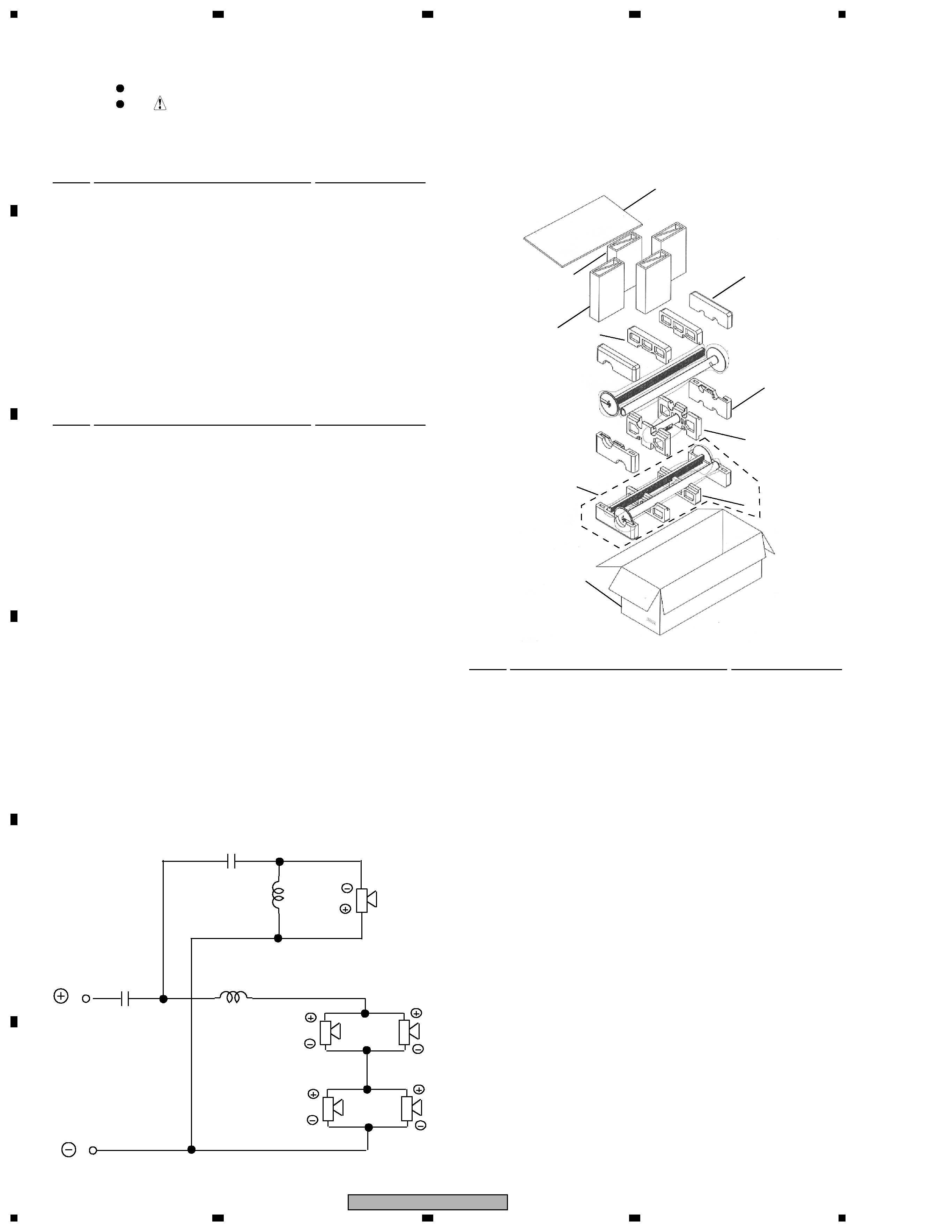
REASSEMBLY AND DISASSEMBLY
The grille is attached to the baffle by its bosses with glue.
To detach it, pry it open by inserting a flat blade tool
between the grille and the cabinet. Be careful not to
damage the grille or the cabinet.
The Network assembly for front and rear speaker is
jointly fixed by glue inside the bottom plate structure. To
detach it, first remove the speaker base and then,
unfasten the 2 screws of the bottom plate.
Woofer units are attached together to the baffle board by
16 external screws. To detach them, unfasten those
screws.
Tweeter is attached to the baffle board by 4 external
screws. To detach it, unfasten those screws.
The network assembly for centre speaker is not a
service part. For reparation of the network, replace the
whole centre speaker system.
Center
Tall Boy x4
Center
Tall Boy x2
S-FC410