ORDER NO.
PIONEER CORPORATION 4-1, Meguro 1-chome, Meguro-ku, Tokyo 153-8654, Japan
PIONEER ELECTRONICS (USA) INC. P.O. Box 1760, Long Beach, CA 90801-1760, U.S.A.
PIONEER EUROPE NV Haven 1087, Keetberglaan 1, 9120 Melsele, Belgium
PIONEER ELECTRONICS ASIACENTRE PTE. LTD. 253 Alexandra Road, #04-01, Singapore 159936
PIONEER CORPORATION 2008
Front
Center
Surround
Subwoofer
S-EV70V
RRV3814
T-ZZR JULY 2008 Printerd in Japan
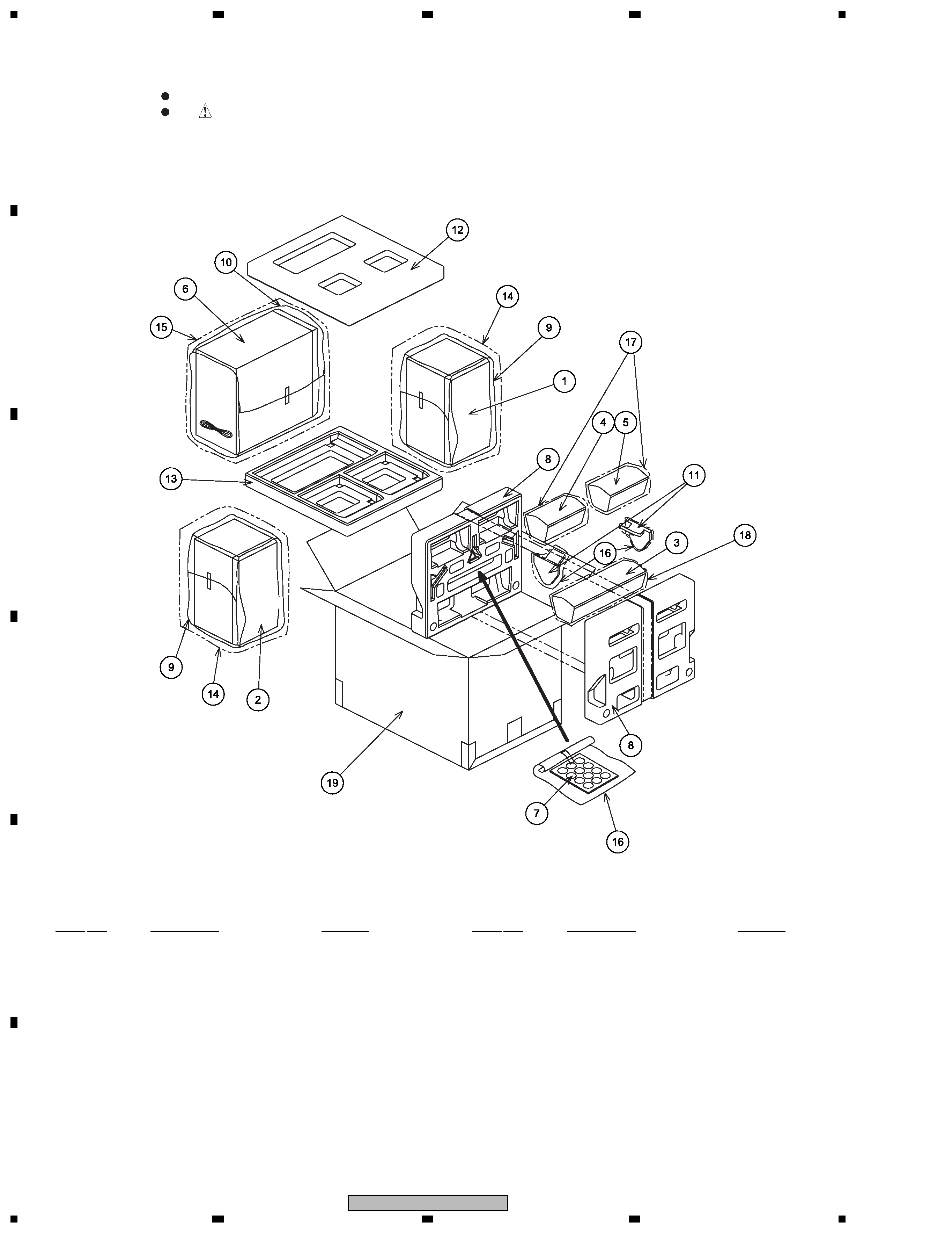
SPEAKER SYSTEM
S-EV70V
/XTM/E
1. REASSEMBLY AND DISASSEMBLY PRECAUTIONS
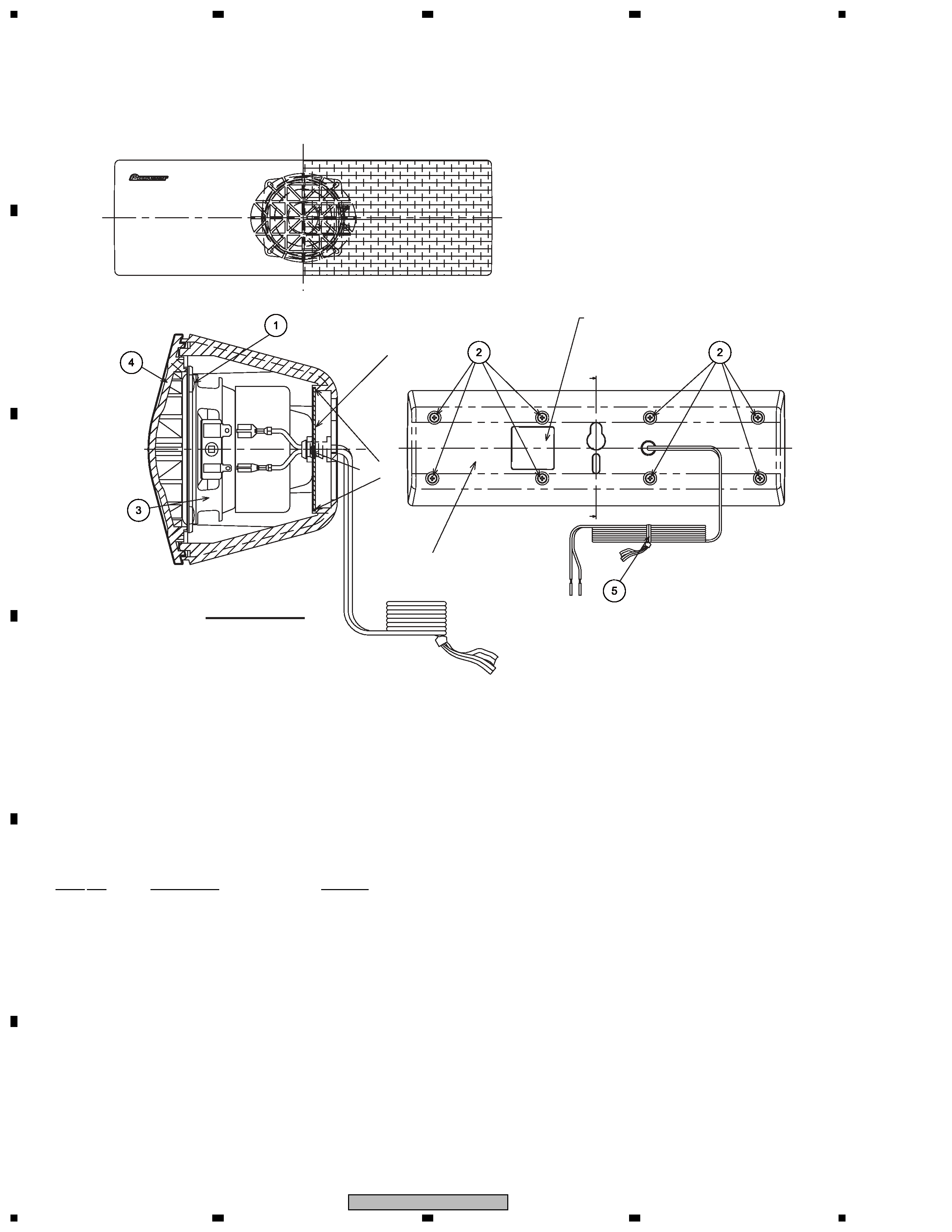
1.1 FRONT SPEAKER
The grille assy is attached to the cosmetic baffle by catches.
Detach by pulling it toward you.
The catch is attached to the cosmetic baffle by press-fitting. To
detach it, insert a sharp-pointed tool like an eyeleteer into each
of side. To attach it, insert the holes of the cosmetic baffle assy
by press-fitting.
The cosmetic baffle is attached to the inner baffle by its bosses.
To detach it, pry it open by inserting a flat blade screwdriver into
lower side.
The woofer is attached to the inner baffle by 4 screws with the
screw heads facing the baffle. To detach it, first remove the
cosmetic baffle, next disconnect the cord from the tweeter.
Then unfasten those screws. When attaching it, face its terminal
upward.
The tweeter is attached to the cosmetic baffle by 2 internal
screws. To detach it, first remove the cosmetic baffle, next
disconnect the cord from the tweeter. Then unfasten those
screws. When attaching it, face its terminal downward.
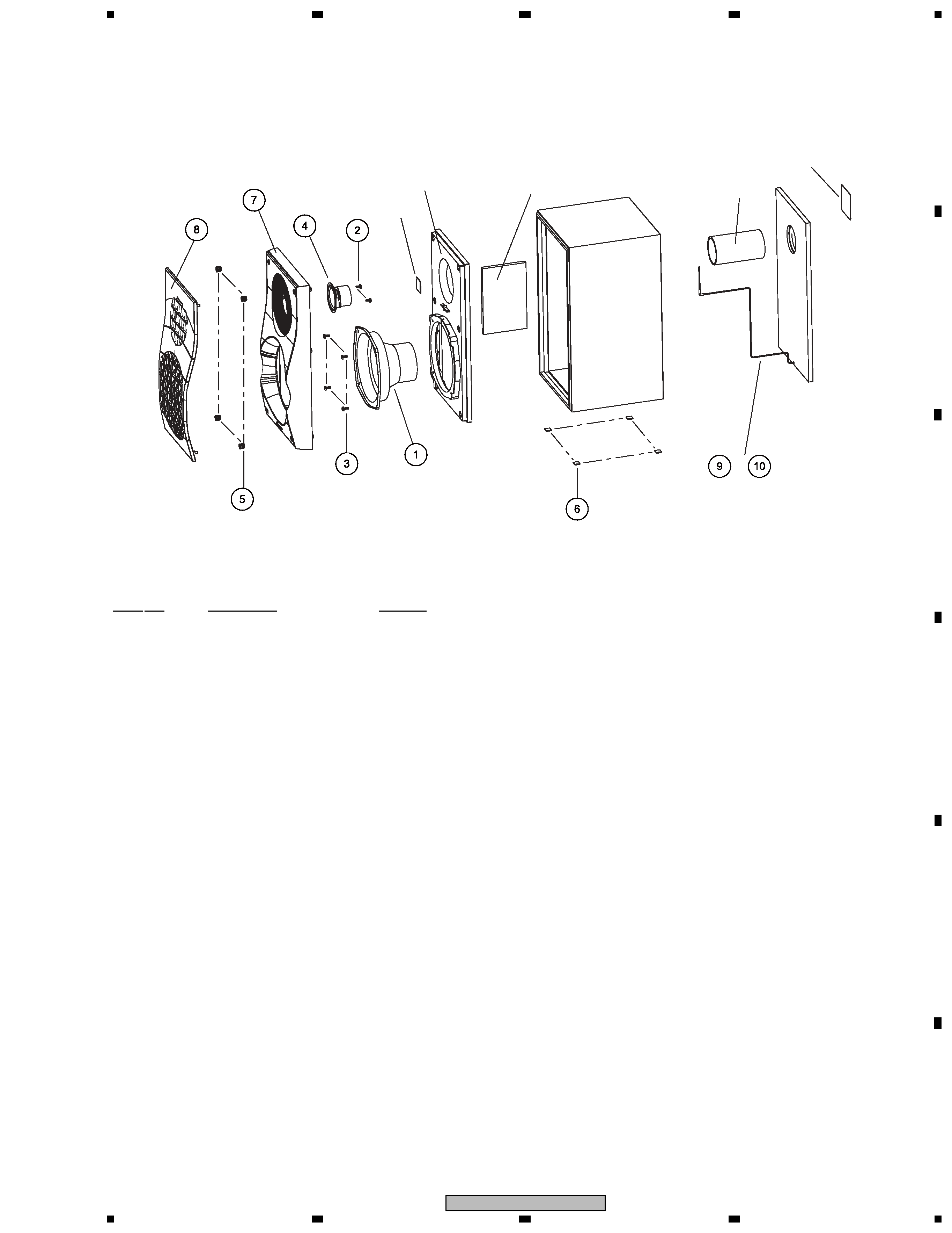
1.2 SURROUND, CENTER SPEAKER
The grille assy is attached to the cabinet by 4 external screws. To
detach it, unfasten those screws. When attaching it, it attaches,
as the connection cord is under the speaker unit.
( Surround )
The grille assy is attached to the cabinet by 8 external screws.
To detach it, unfasten those screws. When attaching it, set the
connection cord under the speaker unit.
( Center )
The speaker unit is attached to the grille by 4 internal screws.
To detach it, first remove the grille assy. Next unfasten those
screws, and remove the cable. When attaching it, face its
terminal leftward. (See to the backside of the grille assy.)
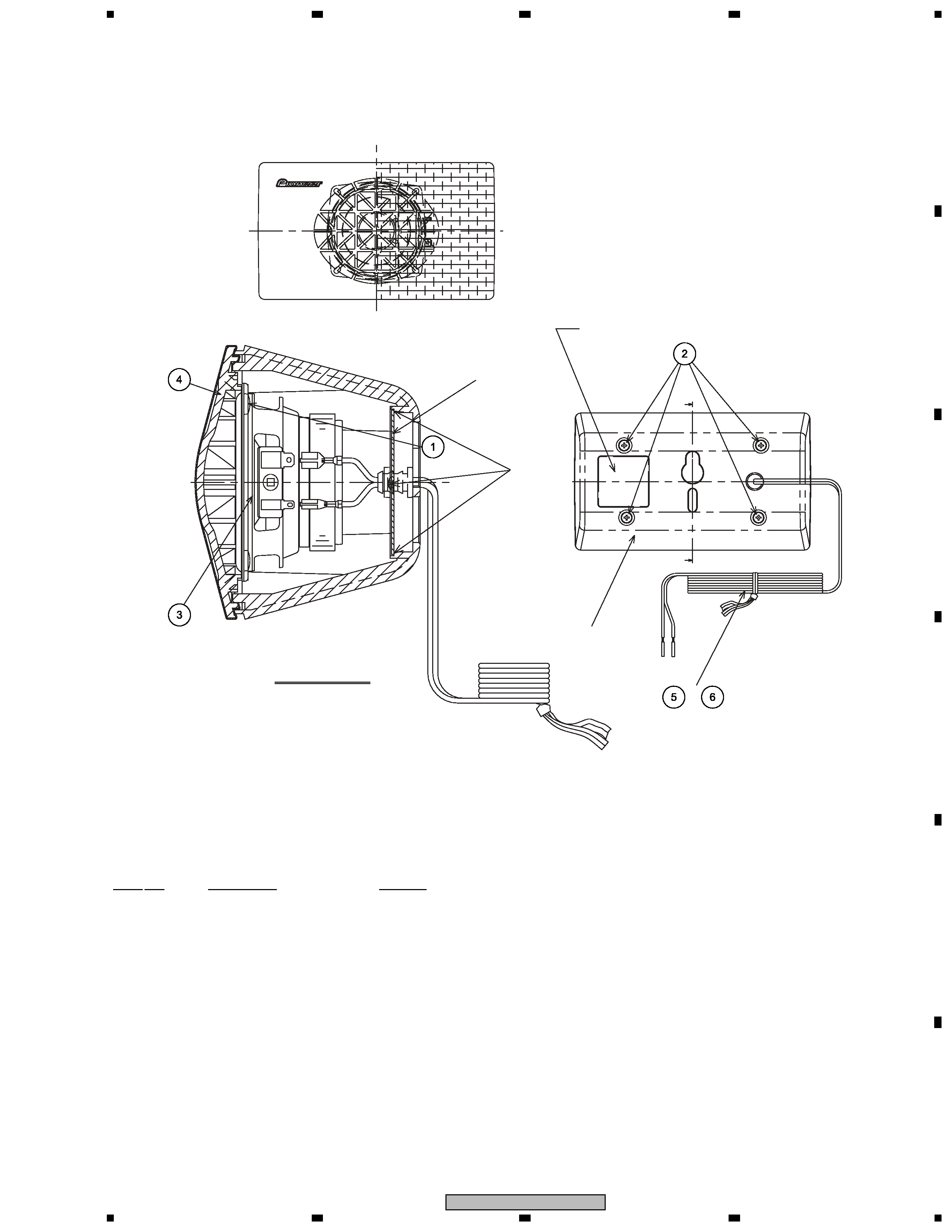
1.3 SUBWOOFER
The cosmetic baffle is attached to the cabinet by its bosses. To
detach it, pry it open by inserting a flat blade screwdriver into
lower slot. To attach it, clean the press-fitting part and apply a
bit of adhesive. Then press it to the baffle.
The woofer is attached to the back board of cabinet by 4 external
screws. To detach it, unfasten those screws. When attaching it,
face its terminal upward.