ORDER NO.
PIONEER CORPORATION 4-1, Meguro 1-chome, Meguro-ku, Tokyo 153-8654, Japan
PIONEER ELECTRONICS (USA) INC. P.O. Box 1760, Long Beach, CA 90801-1760, U.S.A.
PIONEER EUROPE NV Haven 1087, Keetberglaan 1, 9120 Melsele, Belgium
PIONEER ELECTRONICS ASIACENTRE PTE. LTD. 253 Alexandra Road, #04-01, Singapore 159936
PIONEER CORPORATION 2005
RRV3164
T ZZK JUNE 2005 Printed in Japan
SPEAKER SYSTEM
S-EV700V
XJM/E
S-EV700V XJM/NC
Center
Surround
Sub Woofer
Front
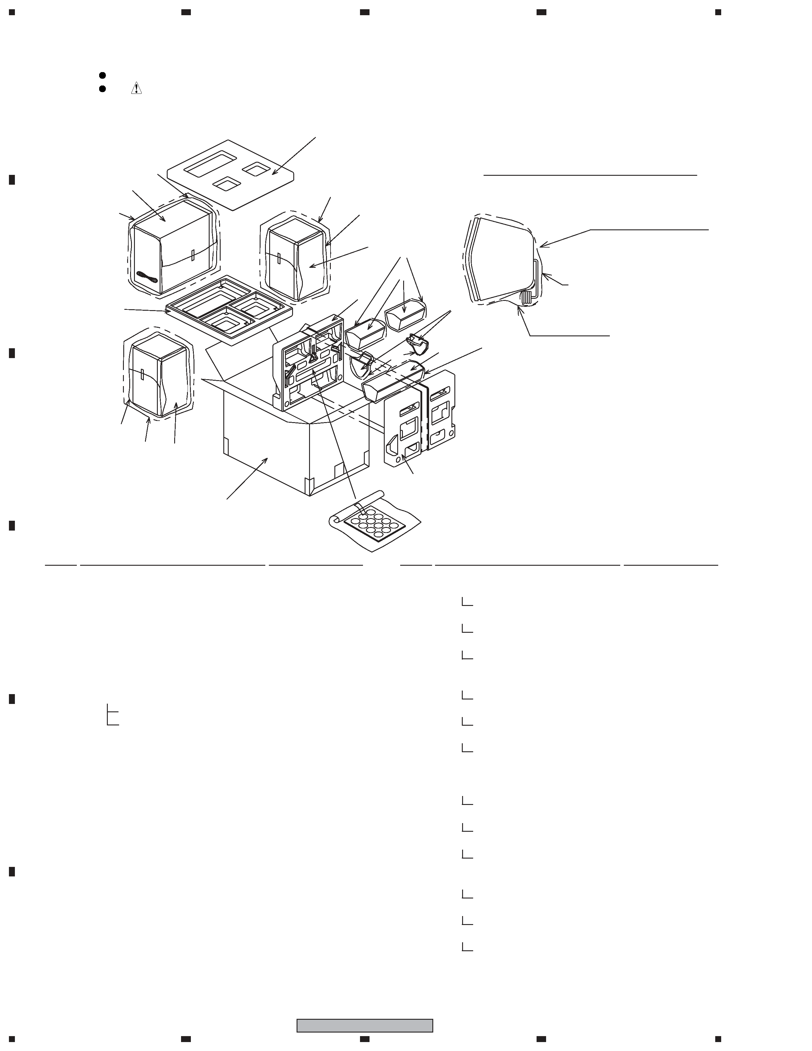
FOR PRECAUTION OF
REASSEMBLY AND DISASSEMBLY
CS Assy ( Front )
The grille assy is attached to the cabinet by catches. Detach by
pulling it toward you.
The catch is attached to the cosmetic baffle by press-fitting. To
detach it, insert a sharp-pointed tool like an eyeleteer into each
of side. To attach it, insert the holes of the cosmetic baffle assy
by press-fitting.
The cosmetic baffle is attached to the baffle by 4 external
screws. To detach it, first remove catches. Then unfasten those
screws.
The woofer is attached to the cosmetic baffle by 4 internal
screws. To detach it, first remove the cosmetic baffle. Then un-
fasten those screws. When attaching it, face its terminal down-
ward.
The tweeter is attached to the cosmetic baffle by 2 internal
screws. To detach it, first remove the cosmetic baffle. Then un-
fasten those screws. When attaching it, face its terminal down-
ward.
CS Assy ( Surround and Center )
The grille assy is attached to the cabinet by 4 external screws.
To detach it, unfasten those screws. When attaching it, it at-
taches, as the connection cord is under the speaker unit.
( Surround )
The grille assy is attached to the cabinet by 8 external screws.
To detach it, unfasten those screws. When attaching it, it at-
taches, as the connection cord is under the speaker unit.
( Center )
The speaker unit is attached to the grille by 4 internal screws.
To detach it, first remove the grille assy. Next unfasten those
screws, and remove the cable. When attaching it, face its termi-
nal leftward. (See to the backside of the grille assy.)
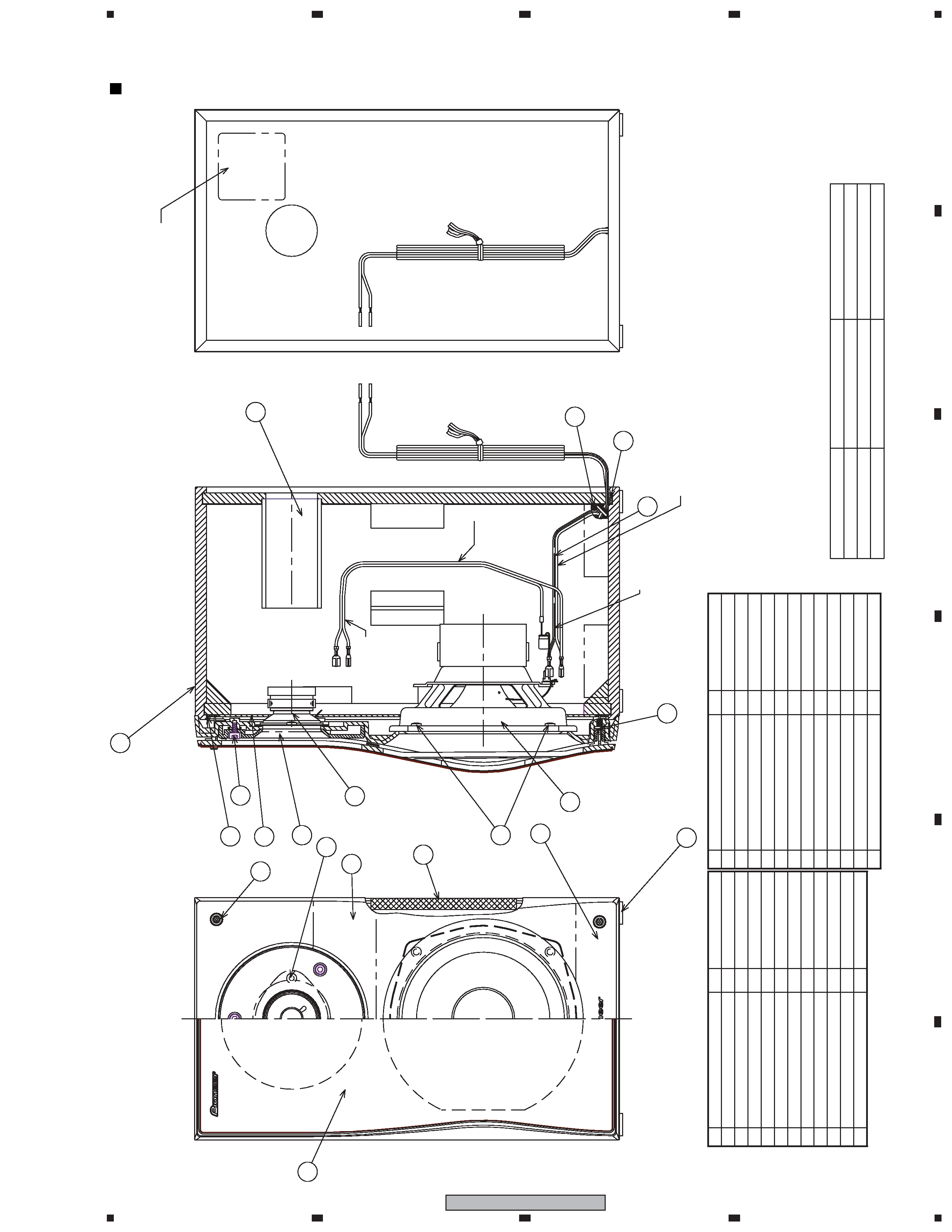
CS Assy ( Subwoofer )
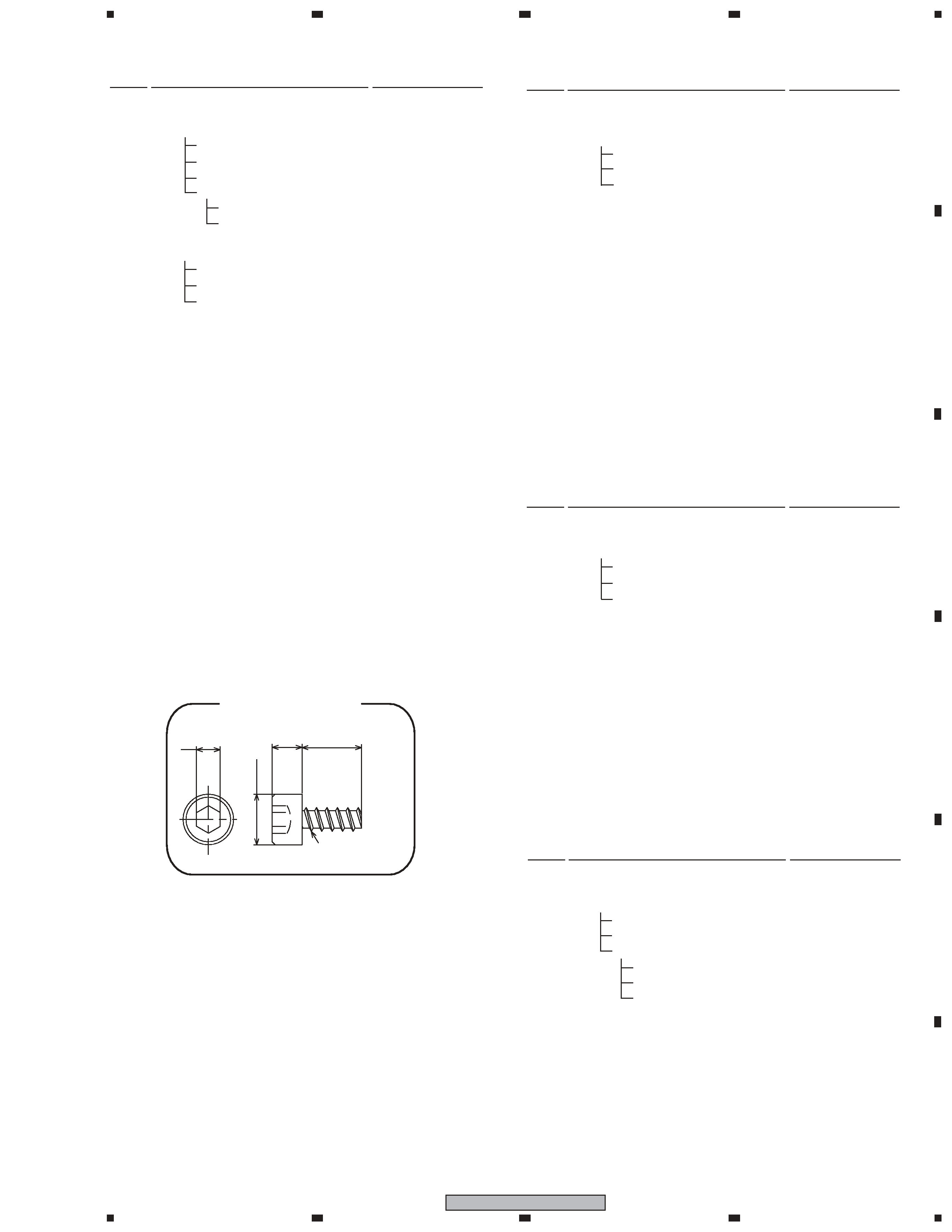
The cosmetic baffle is attached to the cabinet by its bosses. To
detach it, pry it open by inserting a flat blade screwdriver into
lower slot. To attach it, clean the press-fitting part and apply a
bit of adhesive . Then press it to the bafle. (Fig. 1)
The passive radiator is attached to the baffle by 4 external
screws. To detach it, first remove the cosmetic baffle. Then re-
move the passive radiator. When attaching it, face its the rib for
input terminal board toward the vertical direction.
The woofer is attached to the back board of cabinet by 4 exter-
nal screws. To detach it, unfasten those screws. When attaching
it, face its terminal upward.
Fig. 1
apply adhesive
apply adhesive