ORDER NO.
PIONEER CORPORATION 4-1, Meguro 1-chome, Meguro-ku, Tokyo 153-8654, Japan
PIONEER ELECTRONICS (USA) INC. P.O. Box 1760, Long Beach, CA 90801-1760, U.S.A.
PIONEER EUROPE NV Haven 1087, Keetberglaan 1, 9120 Melsele, Belgium
PIONEER ELECTRONICS ASIACENTRE PTE. LTD. 253 Alexandra Road, #04-01, Singapore 159936
PIONEER CORPORATION 2002
RRV2640
T ZZM JULY 2002 Printed in Japan
S-EV51V
S-EV51V
XJI/E
S-EV51V XJI/NC
SPEAKER SYSTEM
Rear
Front
Center
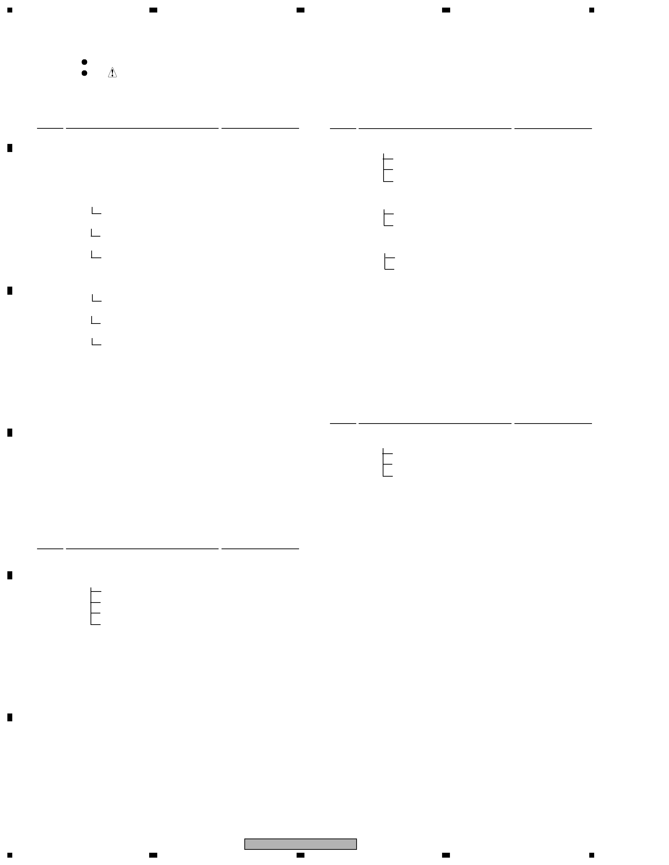
FOR PRECAUTION OF
REASSEMBLY AND DISASSEMBLY
The grille assy is attached to the cabinet by catches. Detach by
pulling it toward you.
The woofer is attatched to the baffle by 4 internal screws. To
detach it, unfasten those screws. When attaching it, face its ter-
minal downward.
The tweeter is attached to the baffle by 2 internal screws. To
detach it, unfasten those screws. When attaching it, face its ter-
minal downward.
The baffle is attached to the cabinet by bosses on both upper
sides, 4 external screws and catches. To detach it, first remove
catches by an eyeleteer and unfasten those screws. Then re-
move bosses by inserting a flat brade screwdriver between the
baffle and the cabinet .
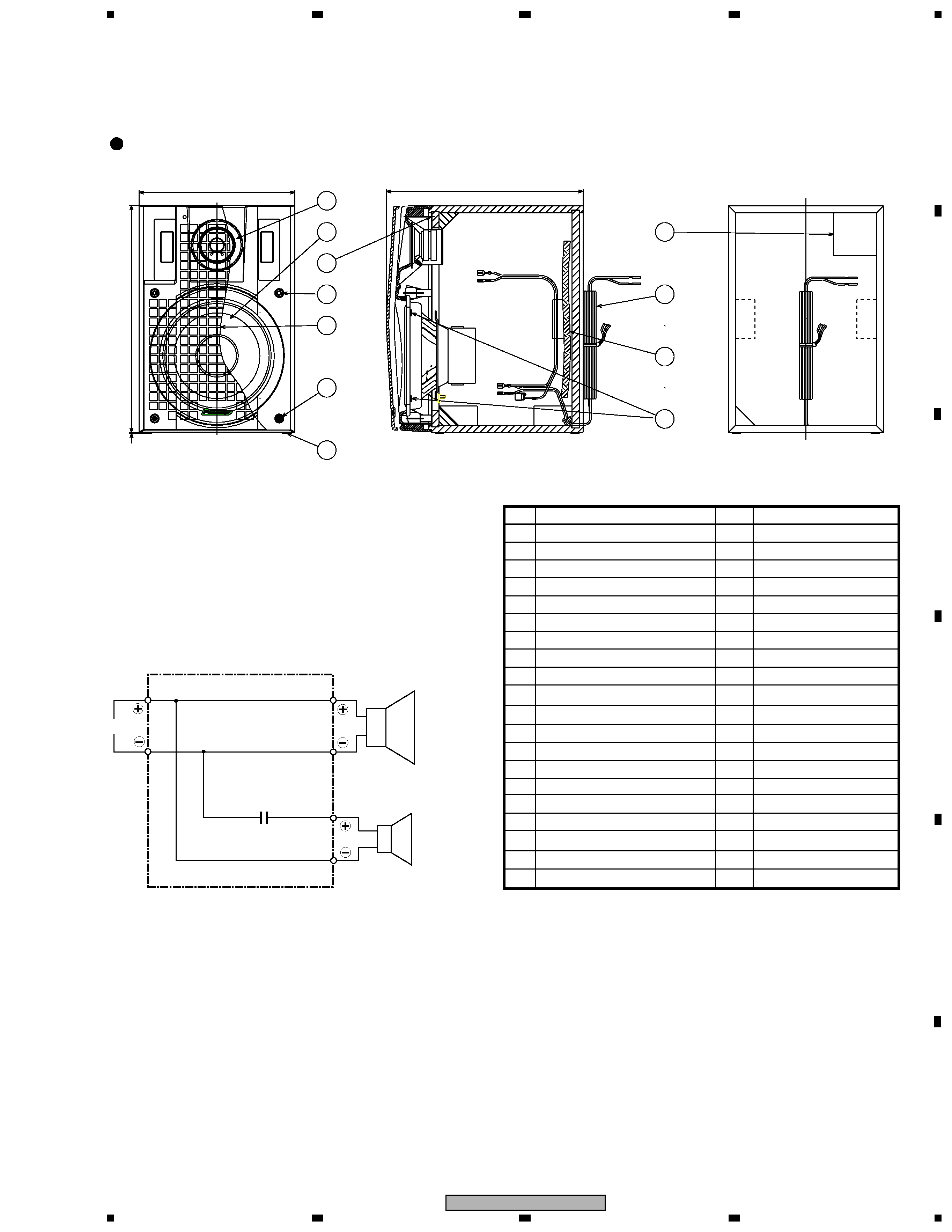
(Front SP)
Each grille assy (L and R) is attached by 4 external screws.
It is attached to the cabinet with the baffle by 2 screws, and
attached to the speaker unit with the baffle by 2 screws.
The speaker unit is attached to the grille and the baffle by 4
internal screws. When attaching it, face its terminal downward.
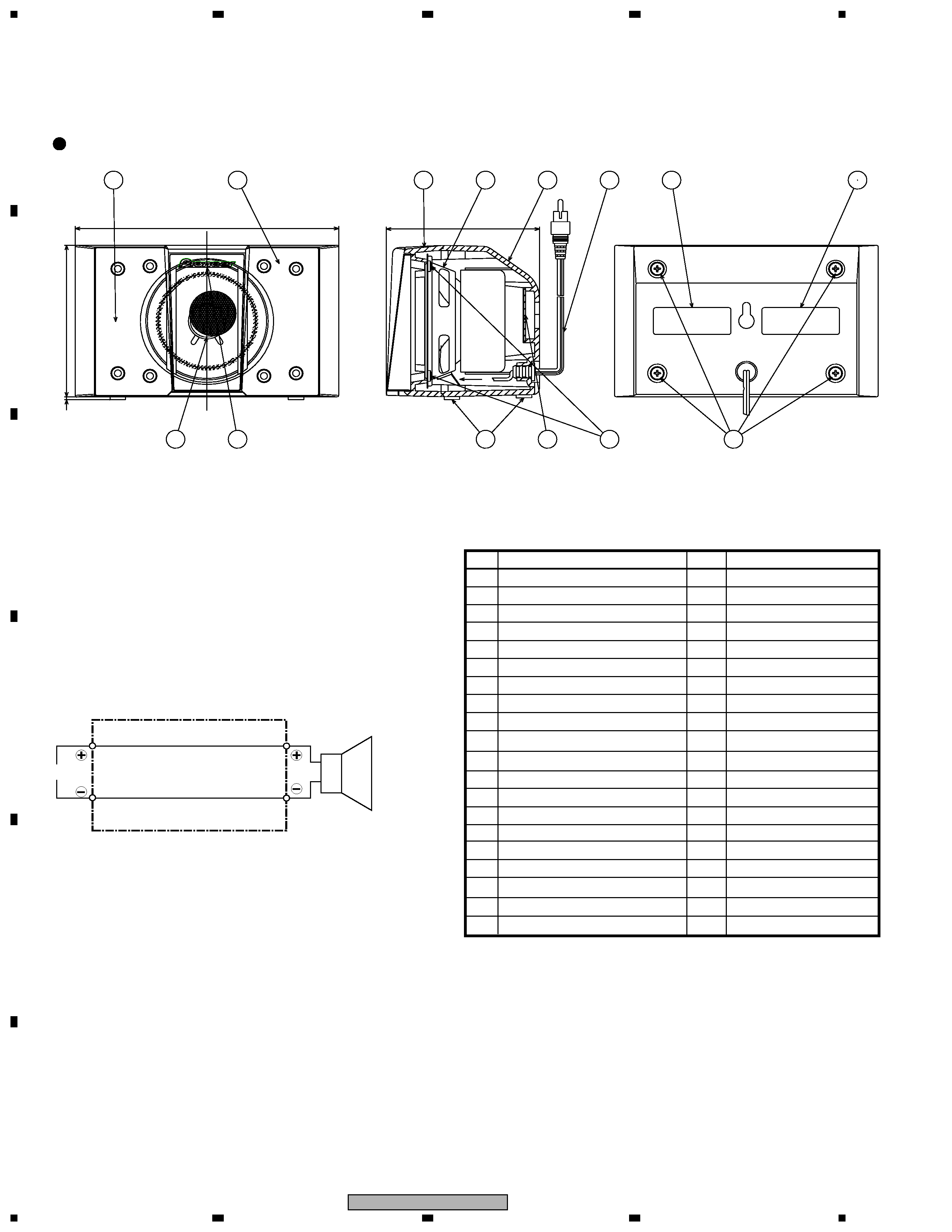
(Center SP)
The grille assy is attached to the cabinet by 4 external screws
from backside.
The speaker is attached to the grille by 4 internal screws. To
detach it, unfasten those screws. When attaching it, face its ter-
minal downward.
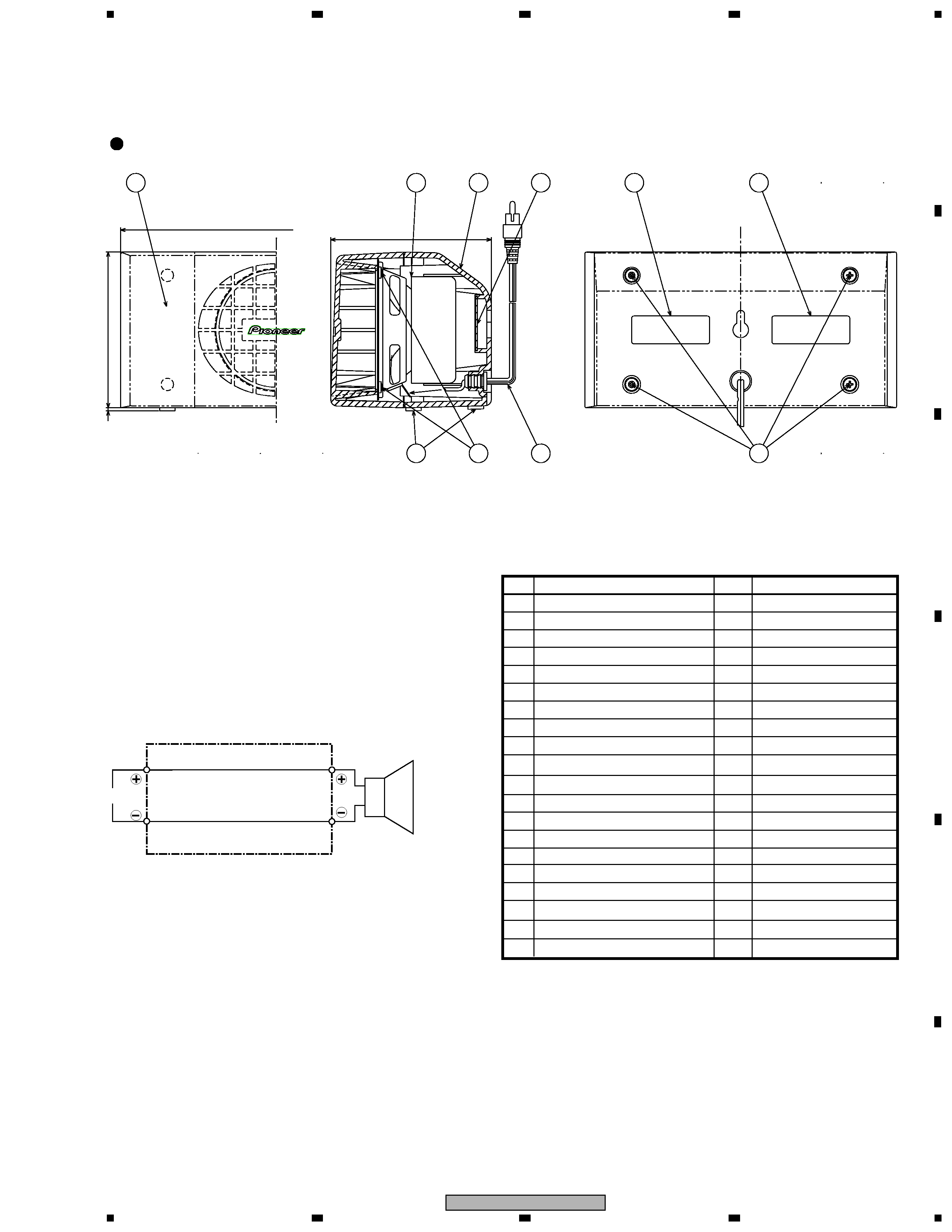
(Rear SP)