Note:
· This unit is for vehicles with a 12-volt battery and
negative grounding. Before installing it in a recre-
ational vehicle, truck, or bus, check the battery
voltage.
· To avoid shorts in the electrical system, be sure to
disconnect the battery cable before beginning
installation.
· Refer to the owner's manual for details on con-
necting the power amp and other units, then make
connections correctly.
· Secure the wiring with cable clamps or adhesive
tape. To protect the wiring, wrap adhesive tape
around them where they lie against metal parts.
· Route and secure all wiring so it cannot touch any
moving parts, such as the gear shift, handbrake,
and seat rails. Do not route wiring in places that
get hot, such as near the heater outlet. If the insu-
lation of the wiring melts or gets torn, there is a
danger of the wiring short-circuiting to the vehicle
body.
· Don't pass the yellow lead through a hole into the
engine compartment to connect to the battery.
This will damage the lead insulation and cause a
very dangerous short.
· Do not shorten any leads. If you do, the protection
circuit may fail to work when it should.
· Never feed power to other equipment by cutting
the insulation of the power supply lead of the unit
and tapping into the lead. The current capacity of
the lead will be exceeded, causing overheating.
· When replacing fuse, be sure to use only fuse of
the rating prescribed on the fuse holder.
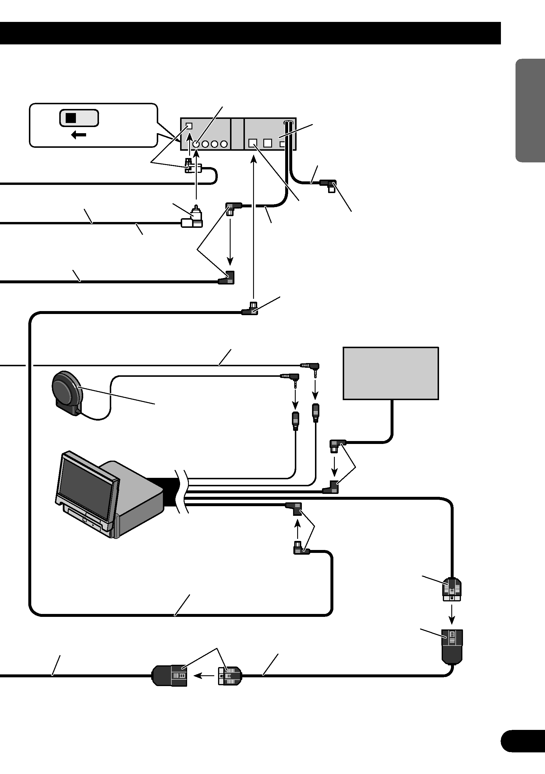
· To prevent incorrect connection, the input side of
the IP-BUS connector is blue, and the output side
is black. Connect the connectors of the same col-
ors correctly.
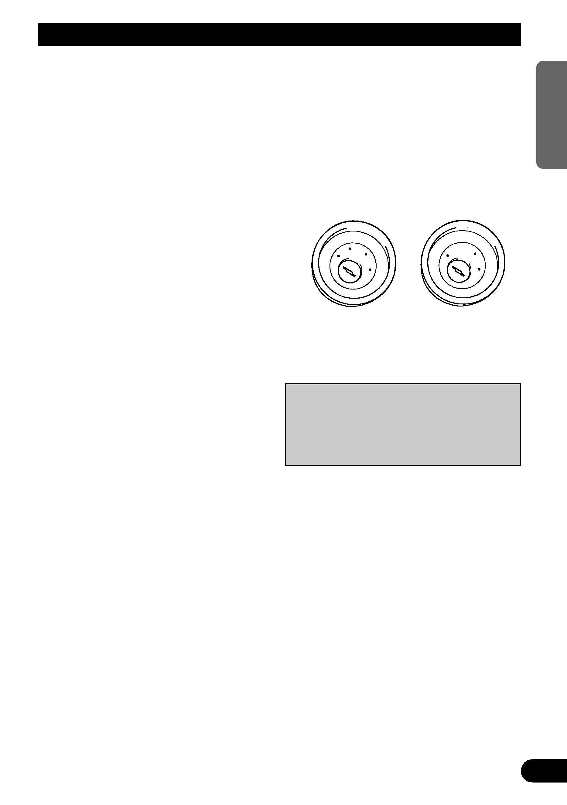
· If this unit is installed in a vehicle that does not
have an ACC (accessory) position on the ignition
switch, the red lead of the unit should be connect-
ed to a terminal coupled with ignition switch
ON/OFF operations. If this is not done, the vehi-
cle battery may be drained when you are away
from the vehicle for several hours. (Fig. 1)
Fig. 1
No ACC position
ACC position
ON
S
T
A
R
T
O
FF
ACC
ON
S
T
A
R
T
O
FF
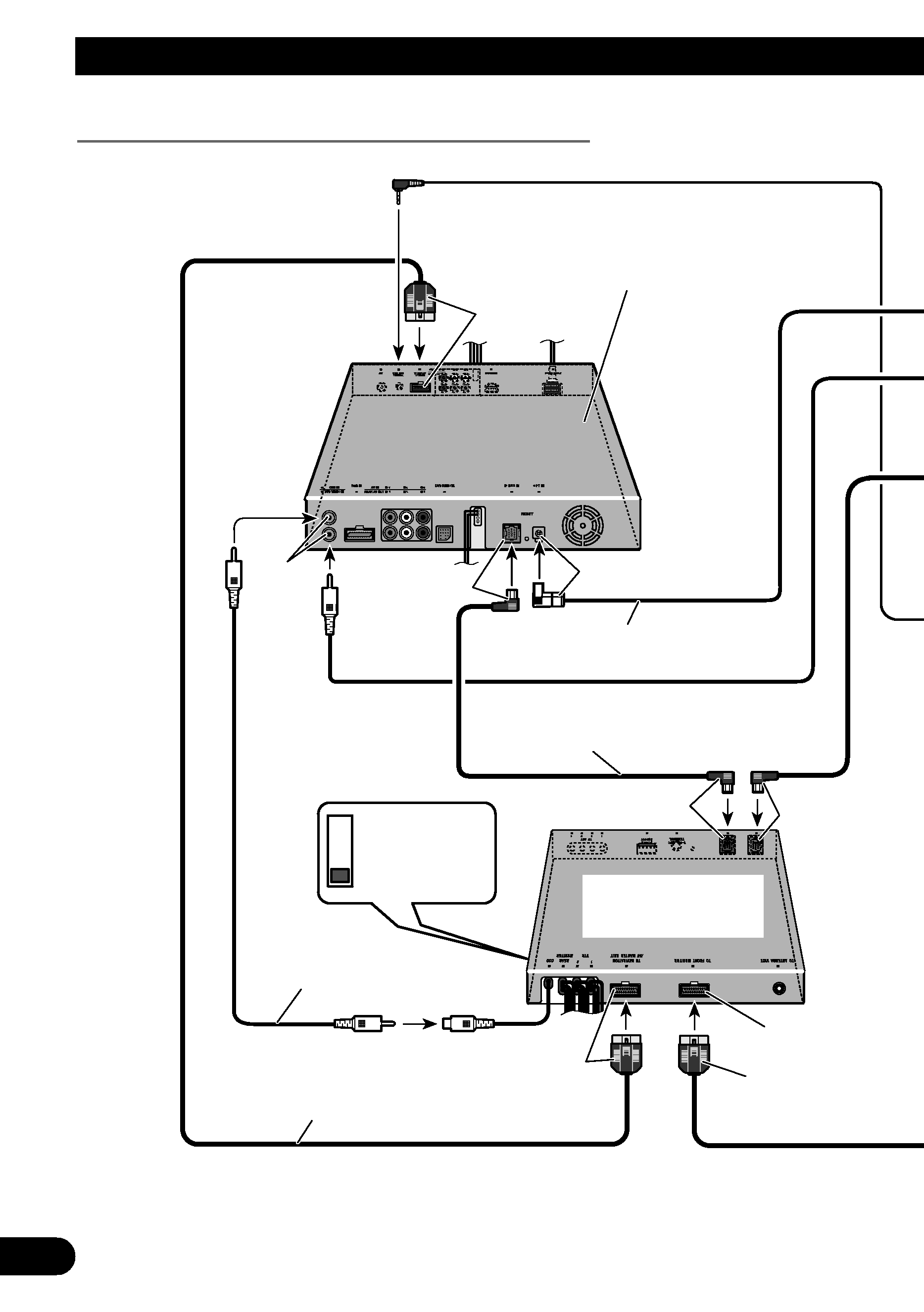
Connecting the Units
2
ENGLISH
ESPA
Ñ
OL
DEUTSCH
FRAN
Ç
AIS
ITALIANO
NEDERLANDS
· Cords for this product and those for other prod-
ucts may be different colors even if they have
the same function. When connecting this product
to another product, refer to the supplied
Installation manuals of both products and con-
nect cords that have the same function.