S-DV830
5
5
678
56
7
8
C
D
F
A
B
E
1. SPECIFICATIONS
(SDS1115)
(SDS1116)
(SDS1117)
(SDS1118)
(SDS1119)
(SEC1563)
(SXG1067)
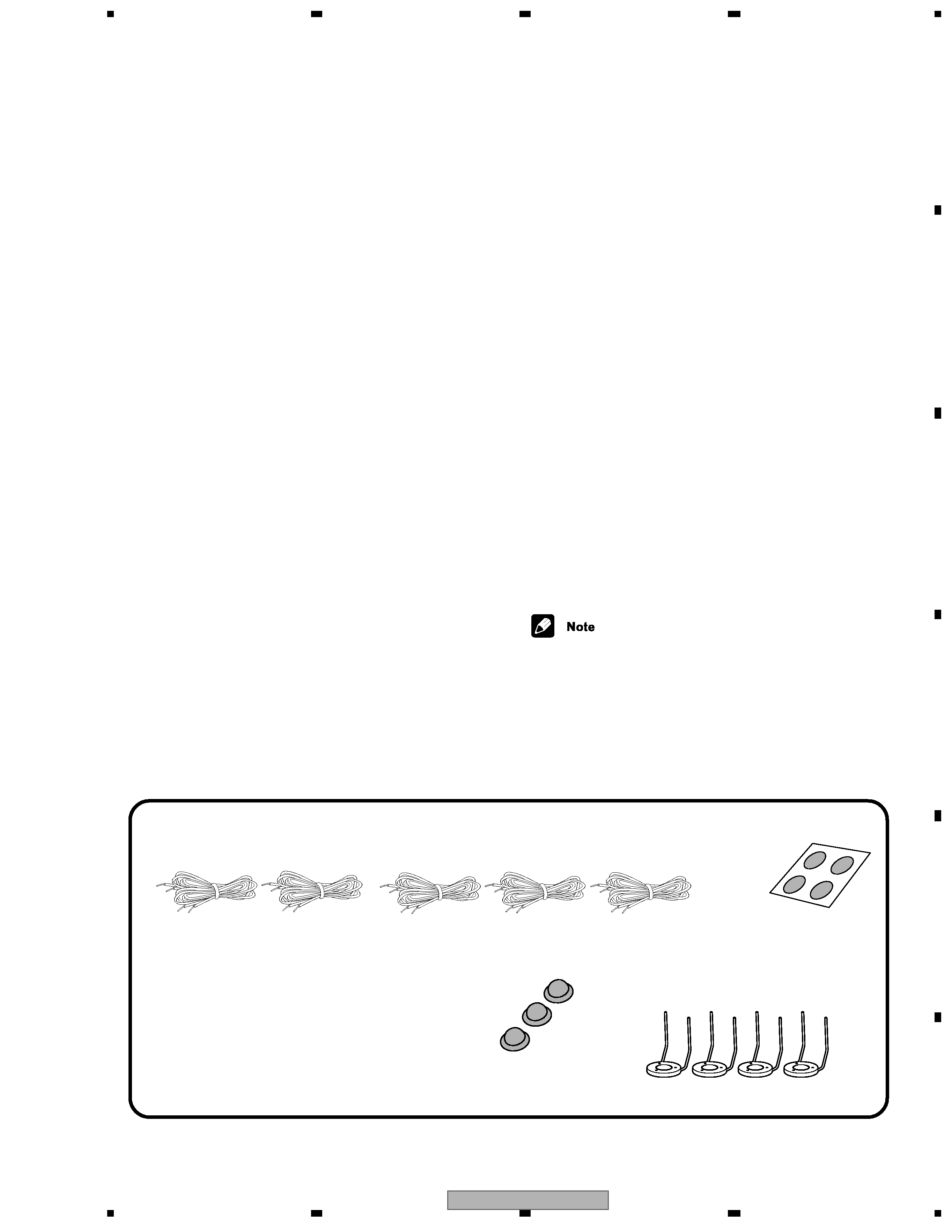
Speaker cords
Speaker Stands x 4
5 m x 3 (for center, front L-R speakers)
Speaker cords
10 m x 2 (for rear L-R speakers)
Non-skid pads
(subwoofer) x4
(SEP1270)
Non-skid pads
(center speaker) x3
accessories
Amplifier Section
Continuous Power (RMS) . . . . . 75 W / channel
. . . . . . . . . . . . . . . . . . . . . (1 kHz, THD 10%, 6
)
Miscellaneous (MY and NV types)
Power Requirements
MY type . . . . . . . . . .AC 220230 V, 50/60 Hz
NV type . . . . . . . . . . . . . . AC 230V, 50/60 Hz
Power Consumption . . . . . . . . . . . . . . . . . 163 W
Power Consumption
in standby mode . . . . . . . . . . . . . . . . . . . 0.48 W
Satellite Speaker System
(S-DV99ST)
Type Sealed, antimagnetic
Speaker . . . . . . . . . . . . . . . . . 8.7 cm (cone type)
. . . . . . . . . . . . . . . . . . . . . . . . 5.2 cm (cone type)
Nominal impedence . . . . . . . . . . . . . . . . . . . . 6
Frequency range . . . . . . . . . . . . . .80 20,000 Hz
Max. input . . . . . . . . . . . . . . . . . . . . 75 W (JEITA)
Front / Surround speakers
Dimensions . . . . . 110 (W) x 59 (D) x 284 (H) cm
Weight . . . . . . . . . . . . . . . . . . . . . . . . . . . . . 0.7 kg
Center speaker
Dimensions . . . . . 284 (W) x 59 (D) x 110 (H) cm
Weight . . . . . . . . . . . . . . . . . . . . . . . . . . . . . 0.7 kg
Powered subwoofer
(S-DV99SW)
Type . . . . . .Bass reflex floor type, antimagnetic
Speaker . . . . . . . . . . . . . . . . . .18 cm (cone type)
Nominal impedence . . . . . . . . . . . . . . . . . . . . 6
Frequency range . . . . . . . . . . . . . . . 25 2300 Hz
Max. input . . . . . . . . . . . . . . . . . . . . 75 W (JEITA)
Dimensions . . . . 192 (W) x 436 (D) x 395 (H) cm
Weight . . . . . . . . . . . . . . . . . . . . . . . . . . . . 12.5 kg
Miscellaneous (KU type)
Power Requirements . . . . . . . . AC 120 V, 60 Hz
Power Consumption. . . . . . . . . . . . . . . . . 178 W
Power Consumption
in standby mode . . . . . . . . . . . . . . . . . . . 0.46 W
Satellite Speaker System
(S-DV830ST)
Type Sealed, antimagnetic
Speaker. . . . . . . . . . . . . . . . . .8.7 cm (cone type)
. . . . . . . . . . . . . . . . . . . . . . . . .5.2 cm (cone type)
Nominal impedence . . . . . . . . . . . . . . . . . . . 6
Frequency range . . . . . . . . . . . . . 80
20,000 Hz
Max. input. . . . . . . . . . . . . . . . . . . . 75 W (JEITA)
Front / Surround speakers
Dimensions . . . . .110 (W) x 59 (D) x 284 (H) cm
4 11/32 (W) x 2 5/16 (D) x 11 3/16 (H) in.
Weight . . . . . . . . . . . . . . . . . . . 0.7 kg / 1 lb. 9 oz
Center speaker
Dimensions . . . . .284 (W) x 59 (D) x 110 (H) cm
11 3/16 (W) x 2 9/32 (D) x 4 11/32 (H) in.
Weight . . . . . . . . . . . . . . . . . . . 0.7 kg / 1 lb. 9 oz
Powered subwoofer (S-DV830SW)
Type . . . . . . Bass reflex floor type, antimagnetic
Speaker. . . . . . . . . . . . . . . . . . 18 cm (cone type)
Nominal impedence . . . . . . . . . . . . . . . . . . . 6
Frequency range . . . . . . . . . . . . . .
25 2300 Hz
Max. input. . . . . . . . . . . . . . . . . . . . 75 W (JEITA)
Dimensions . . . .192 (W) x 436 (D) x 395 (H) cm
7 9/16 (W) x 17 5/32 (D) x 15 9/16 (H) in.
Weight . . . . . . . . . . . . . . . . . 12.5 kg / 27 lb. 9 oz
·Specifications and design subject to
possible modification without notice, due
to improvements.