ORDER NO.
PIONEER CORPORATION 4-1, Meguro 1-chome, Meguro-ku, Tokyo 153-8654, Japan
PIONEER ELECTRONICS (USA) INC. P.O. Box 1760, Long Beach, CA 90801-1760, U.S.A.
PIONEER EUROPE NV Haven 1087, Keetberglaan 1, 9120 Melsele, Belgium
PIONEER ELECTRONICS ASIACENTRE PTE. LTD. 253 Alexandra Road, #04-01, Singapore 159936
PIONEER CORPORATION 2005
RRV3198
T ZZK JUNE 2005 Printed in Japan
FOR PRECAUTION OF
REASSEMBLY AND DISASSEMBLY
SPEAKER SYSTEM
S-DV434ST
XJC/TA
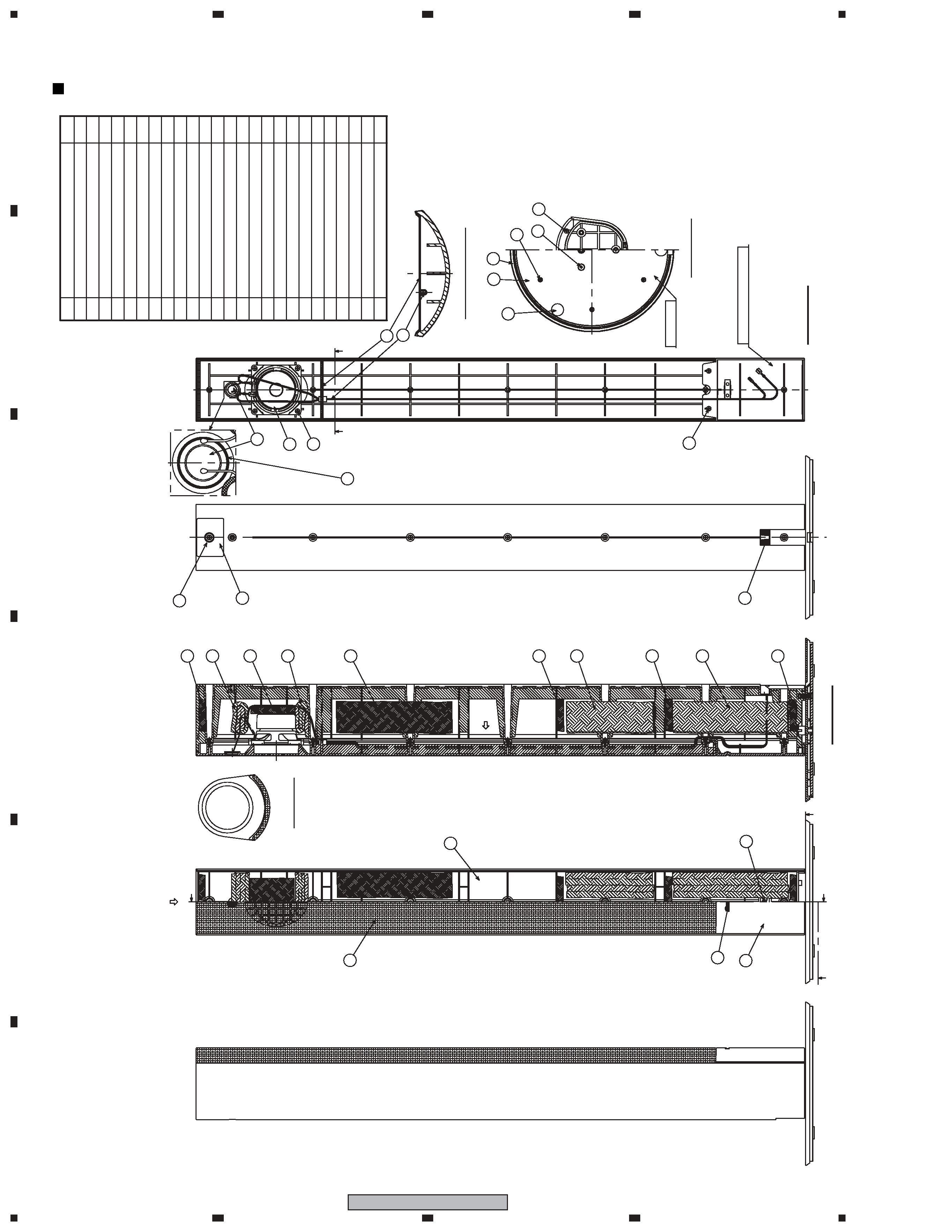
CS Assy ( Front )
The grille assy is attached to the cabinet by 9 external screws.
To detach it, first remove 3 screws of connection part with the
base assy. Next remove 2 screws of the cosmetic plate assy
lower side. Next remove 7 screws of the cabinet. Then carefully
disconnect the wires of the woofer mounted on the grille assy
and input terminal. To detach the cosmetic plate assy, remove 2
screws of connection part with the grille assy.
The woofer is attached to the grille by 4 internal screws. To
detach it, first unfasten those screws. Next remove the cable.
When attaching it, face its terminal upward.
The tweeter is attached to the baffle by adhesives. To exchange
the tweeter, do it with the grille assy.
The cosmetic plate assy is attached to the grille assy by 2 inter-
nal screws. To detach it, first remove the grille assy. Next un-
fasten those screws.
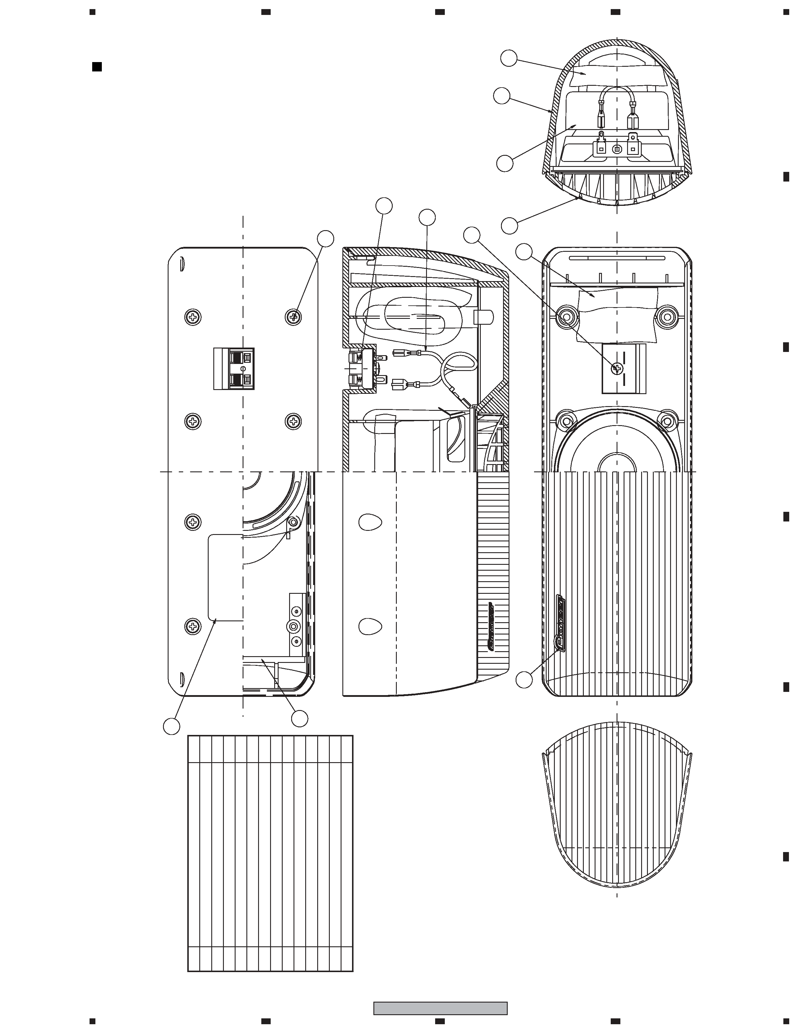
CS Assy ( Surround )
The grille assy is attached to the cabinet by its bosses. To de-
tach it, pry it open by inserting a flat blade screw driver into
lower slot. To attach it, press it to the inner baffle.
The speaker unit is attached to the inner baffle by 4 external
screws. To detach it, first remove the grille assy. Next unfasten
those screws, and remove the cable. When attaching it, face its
terminal downward.
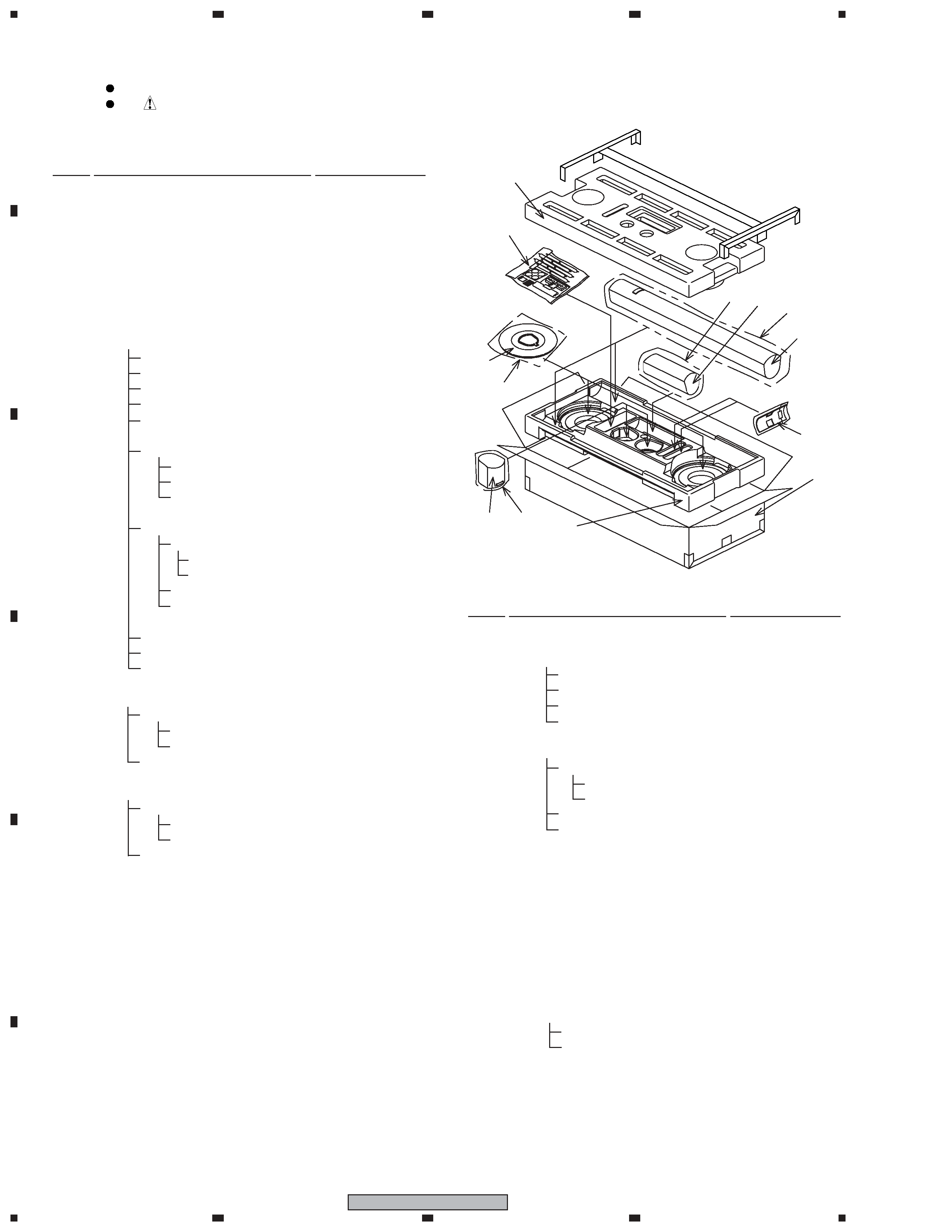
CS Assy ( Center )
The grille assy is attached to the cabinet by 8 external screws.
To detach it ,unfasten those screws.
The speaker unit, together with the grille assy, is attached to the
cabinet by 4 external screws. To detach it, first remove the
grille assy. Next remove the cabinet. Then remove the cable.
When attaching it, face its terminal toward the input terminal.
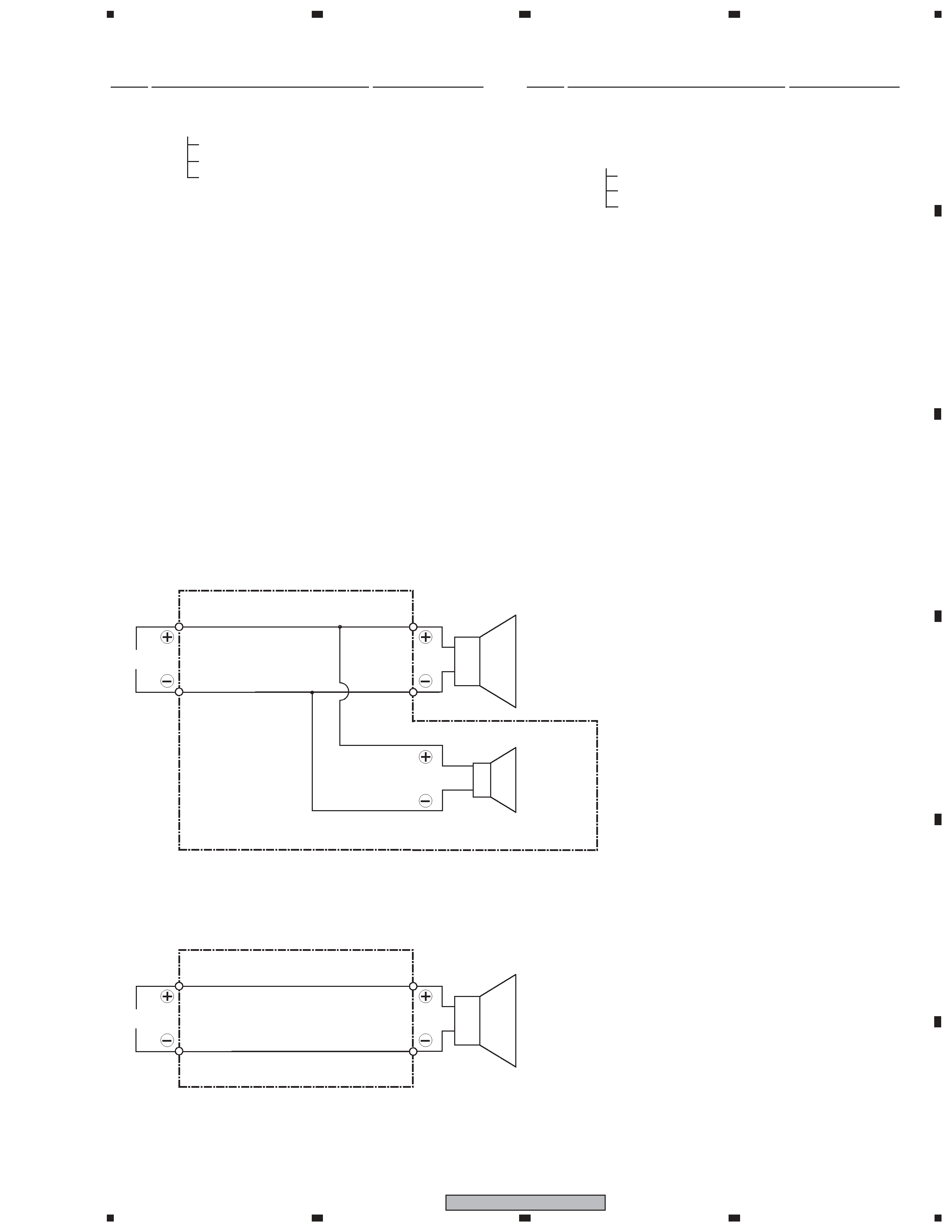
Center
Front
Surround