ORDER NO.
PIONEER CORPORATION 4-1, Meguro 1-chome, Meguro-ku, Tokyo 153-8654, Japan
PIONEER ELECTRONICS (USA) INC. P.O. Box 1760, Long Beach, CA 90801-1760, U.S.A.
PIONEER EUROPE NV Haven 1087, Keetberglaan 1, 9120 Melsele, Belgium
PIONEER ELECTRONICS ASIACENTRE PTE. LTD. 253 Alexandra Road, #04-01, Singapore 159936
PIONEER CORPORATION 2008
S-DV385
RRV3733
T-ZZR APR. 2008 Printed in Japan
S-DV385
SXTW/WL5
SPEAKER SYSTEM
1. REASSEMBLY AND DISASSEMBLY PRECAUTIONS
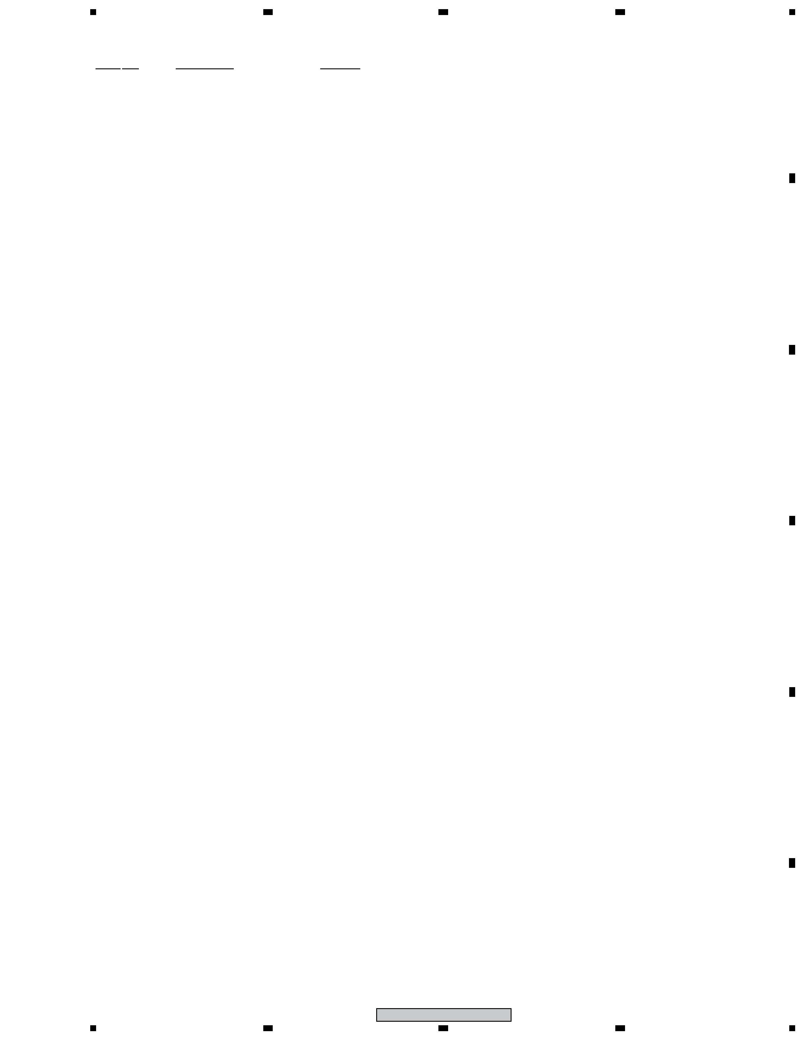
1.1 FRONT/CENTER/SURROUND SPEAKER
The grille is attached to the cabinet by 4 external screws.
To detach it, unfasten those screws.
The speaker unit is attached together with the grille assy to the
cabinet by 4 external screws. To detach it, first unfasten those
screws. Next remove the cabinet. Then remove the cable.
When attaching it, face its terminal downward.
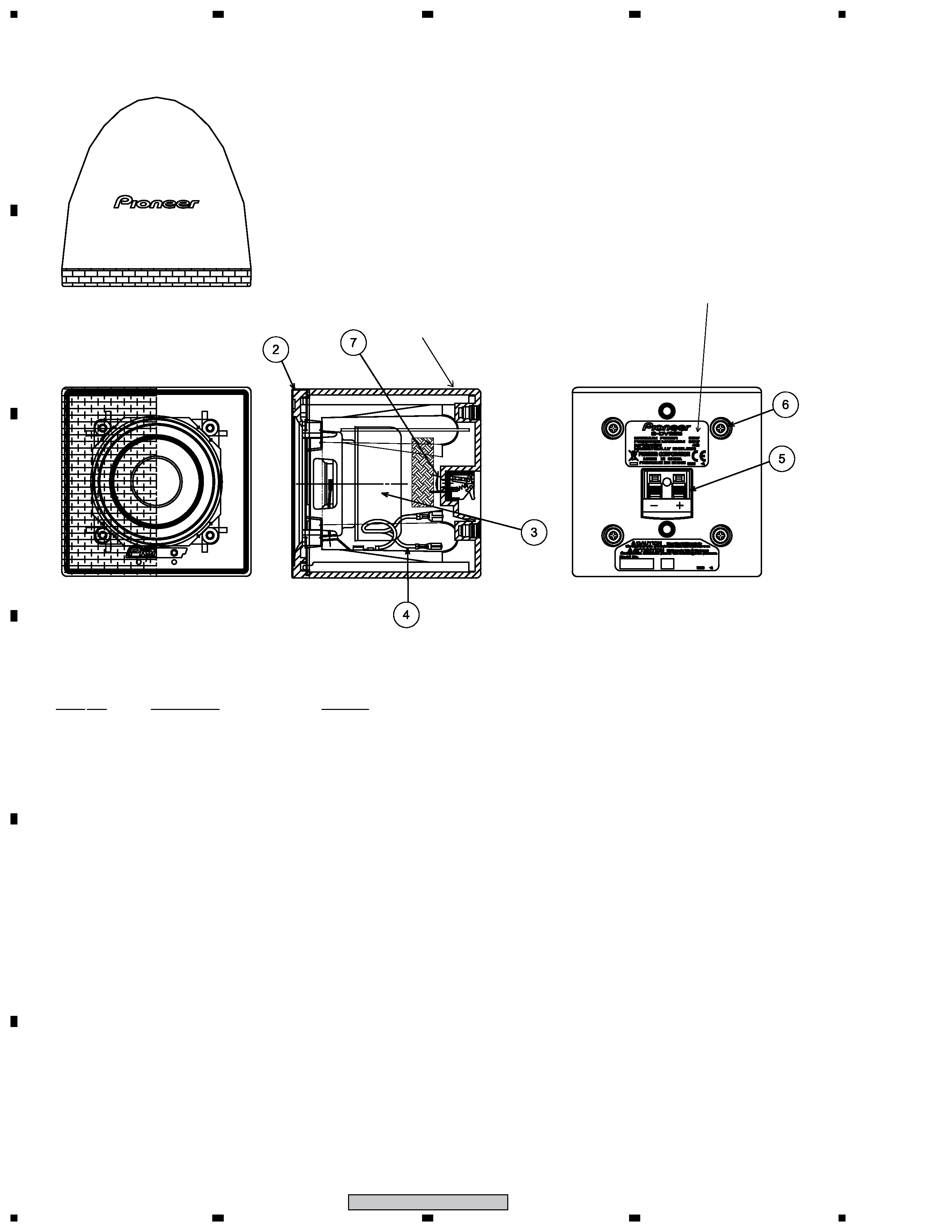
1.2 SUBWOOFER
The speaker unit is attached to the bottom by 4 external
screws. To detach it, unfasten those screws. When attaching it,
face its terminal backward.
The cosmetic baffle assy is attached to the baffle board by
press-fitting. To detach it, pry it open by inserting a flat blade
screwdriver into lower slot.