ORDER NO.
PIONEER CORPORATION 4-1, Meguro 1-chome, Meguro-ku, Tokyo 153-8654, Japan
PIONEER ELECTRONICS (USA) INC. P.O. Box 1760, Long Beach, CA 90801-1760, U.S.A.
PIONEER EUROPE NV Haven 1087, Keetberglaan 1, 9120 Melsele, Belgium
PIONEER ELECTRONICS ASIACENTRE PTE. LTD. 253 Alexandra Road, #04-01, Singapore 159936
PIONEER CORPORATION 2005
RRV3146
T ZZR APR. 2005 Printed in Japan
S-DV350ST
XTW/UC
FOR PRECAUTION OF
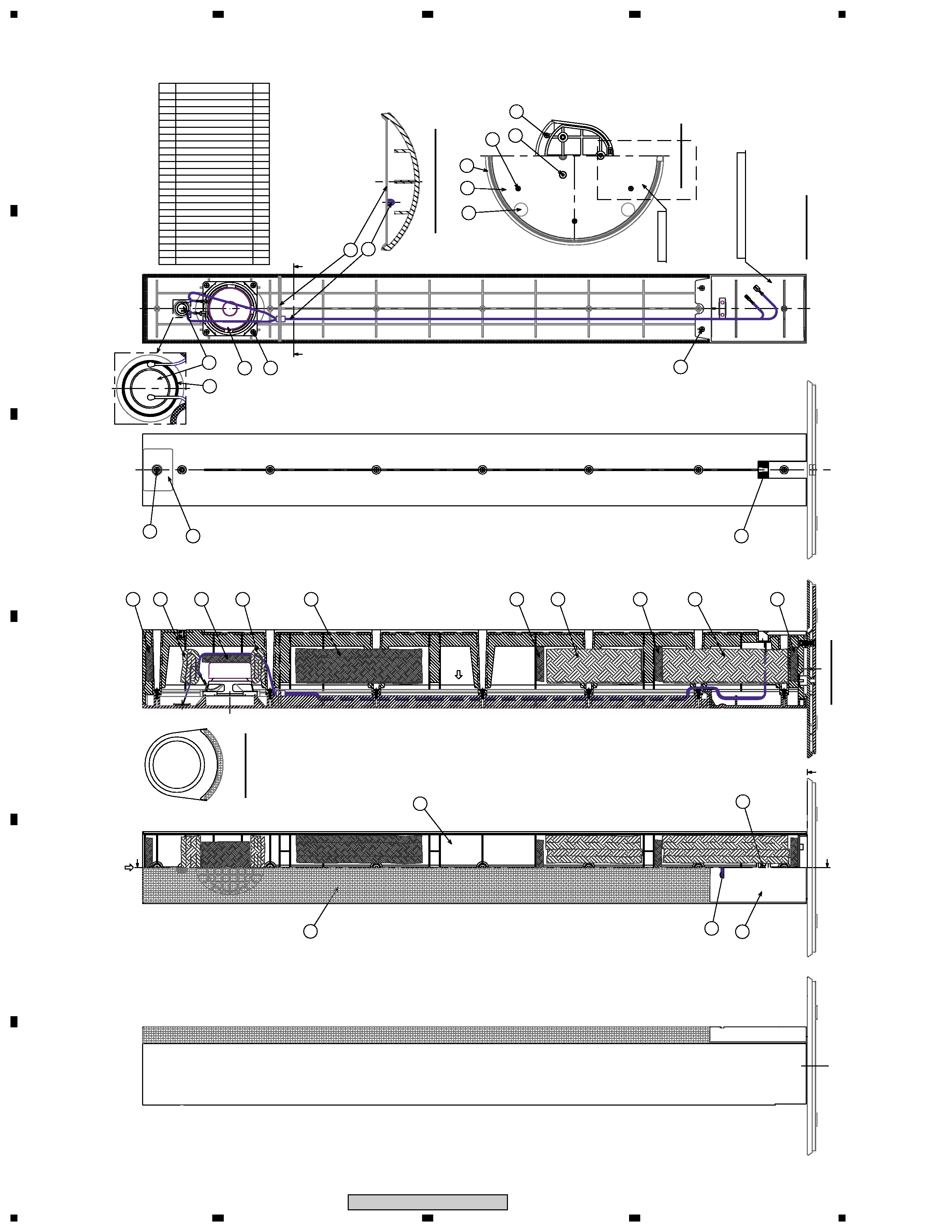
REASSEMBLY AND DISASSEMBLY
The grille assy and the cosmetic plate assy are attached to the
cabinet by 9 external screws. To detach the grille assy and the
cosmetic plate assy, first remove 3 screws of a connection part
with the base assy. Next remove 2 screws of the cosmetic plate
assy lower side. Next remove 7 screws of the cabinet. Then
carefully disconnect the wires of the woofer mounted on the
grille assy and input terminal.
To detach the cosmetic plate assy, remove 2 screws of connec-
tion part with grille assy.
The woofer is attached to the grille assy by 4 internal screws.
To detach it, unfasten there screws. When attaching it, face its
terminal upward.
When exchange the tweeter, do it with the grille assy.
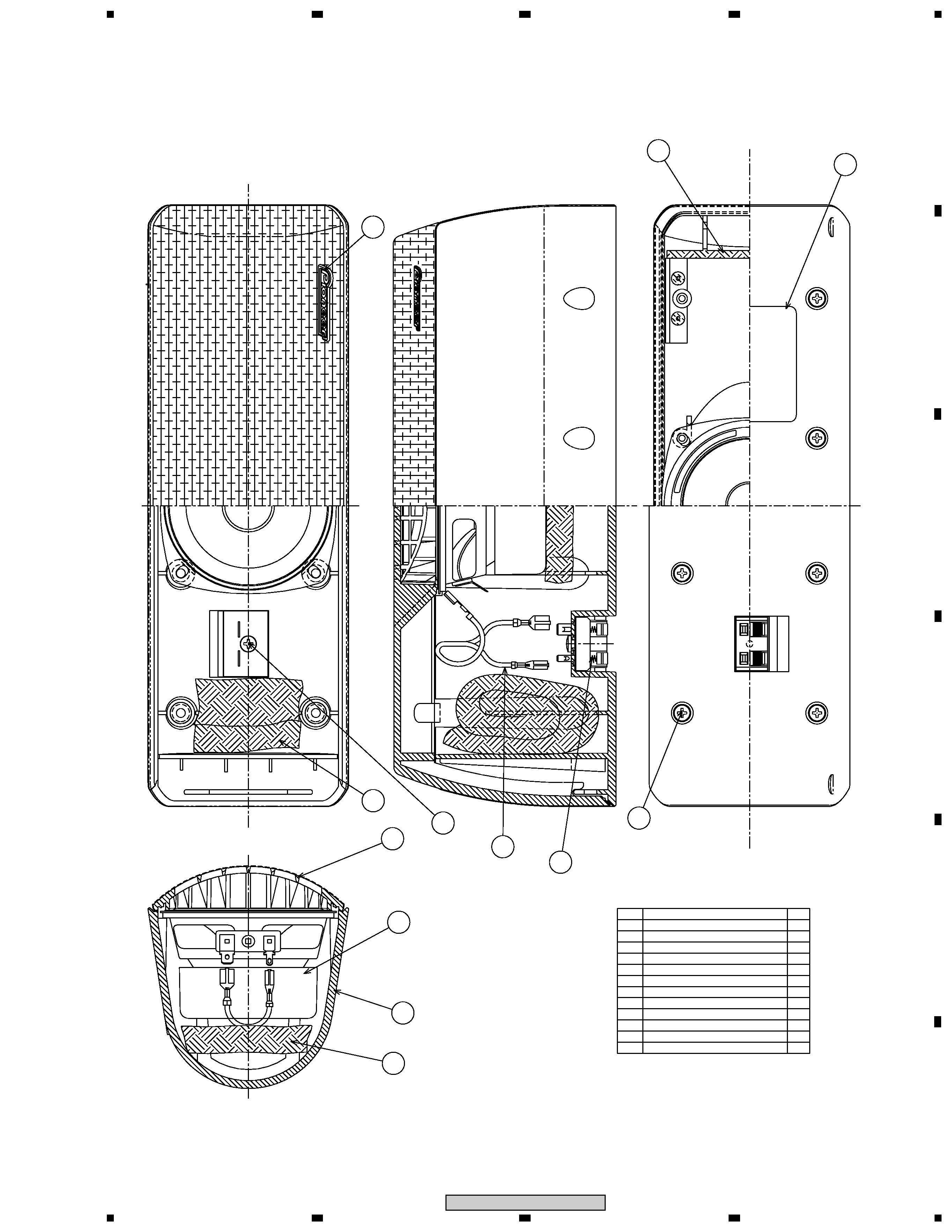
CS Assy ( Surround Speaker )
The grille assy is attached to the cabinet by its bosses. To de-
tach it, pry it open by inserting a flat blade screwdriver into
downside of it.
The speaker unit is attached to the grille by 4 internal screws.
To detach it, first unfasten those screws. Next remove cabinet.
Then remove the cable.
When attaching it, face its terminal downward.
CS Assy ( Center Speaker )
The grille assy is attached to the cabinet by 8 screws. To detach
it ,unfasten those screws.
The speaker unit, together with the grille, is attached to the
cabinet by 4 external screws.
To detach it, unfasten those screws. To detach it, first remove
the cabinet. Then remove the cable.
When attaching it, face its terminal toward the input terminal.
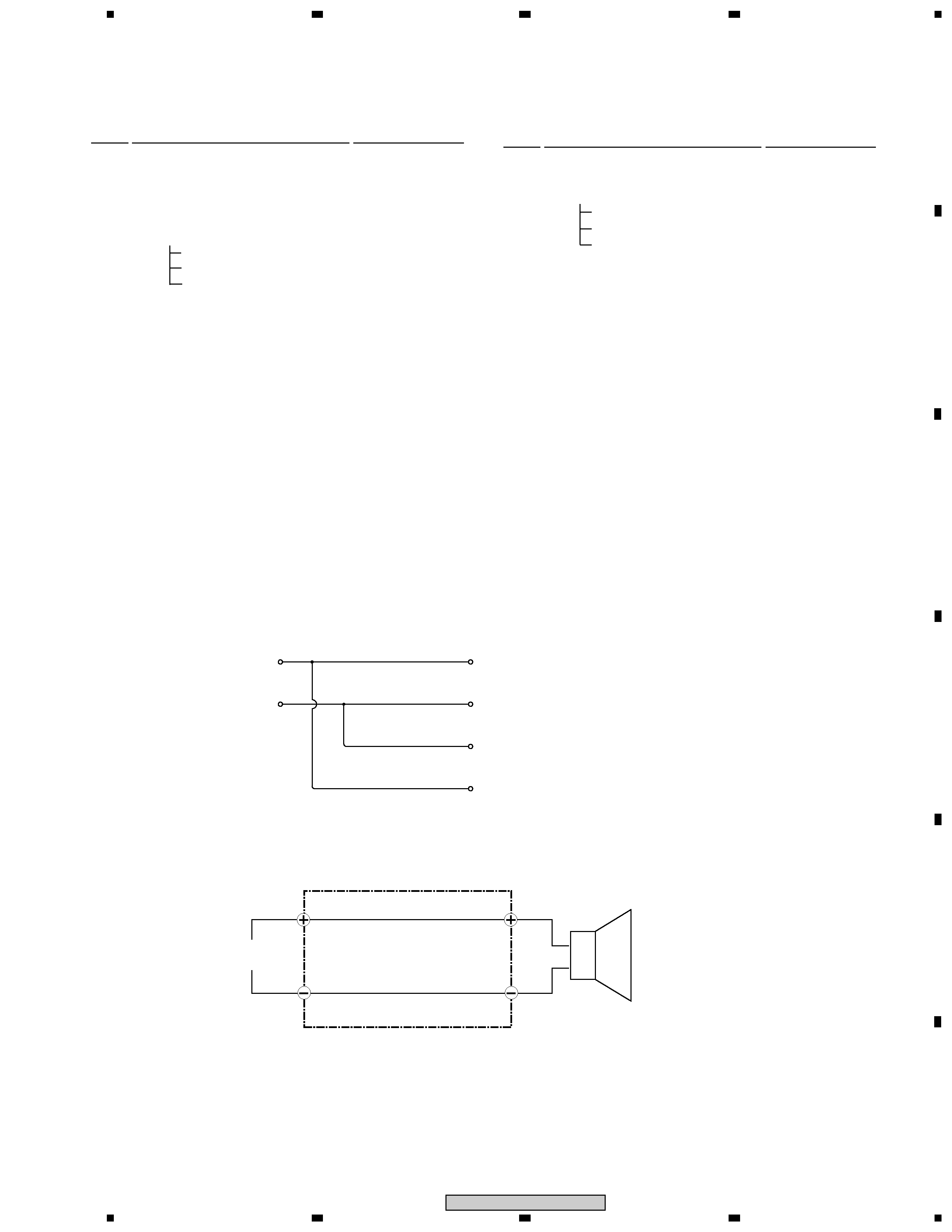
SPEAKER SYSTEM
Surround
Center
Front
65S
This service manual is intended for qualified service technicians; it is not meant
for the casual do-it-yourselfer. Qualified technicians have the necessary test
equipment and tools, and have been trained to properly and safely repair complex
products such as those covered by this manual.
Improperly performed repairs can adversely affect the safety and reliability
of the product and may void the warranty. If you are not qualified to perform the
repair of this product properly and safely, you should not risk trying to do so and
refer the repair to a qualified service technician.
WARNING
This product contains lead in solder and certain electrical parts contain chemicals
which are known to the state of California to cause cancer, birth defects or other
reproductive harm.
Health & Safety Code Section 25249.6 Proposition 65