ORDER NO.
PIONEER CORPORATION 4-1, Meguro 1-chome, Meguro-ku, Tokyo 153-8654, Japan
PIONEER ELECTRONICS (USA) INC. P.O. Box 1760, Long Beach, CA 90801-1760, U.S.A.
PIONEER EUROPE NV Haven 1087, Keetberglaan 1, 9120 Melsele, Belgium
PIONEER ELECTRONICS ASIACENTRE PTE. LTD. 253 Alexandra Road, #04-01, Singapore 159936
PIONEER CORPORATION 2003
RRV2767
T ZZM MAY 2003 Printed in Japan
S-DV313
S-DV313
XTW/EW
SPEAKER SYSTEM
FOR PRECAUTION OF
REASSEMBLY AND DISASSEMBLY
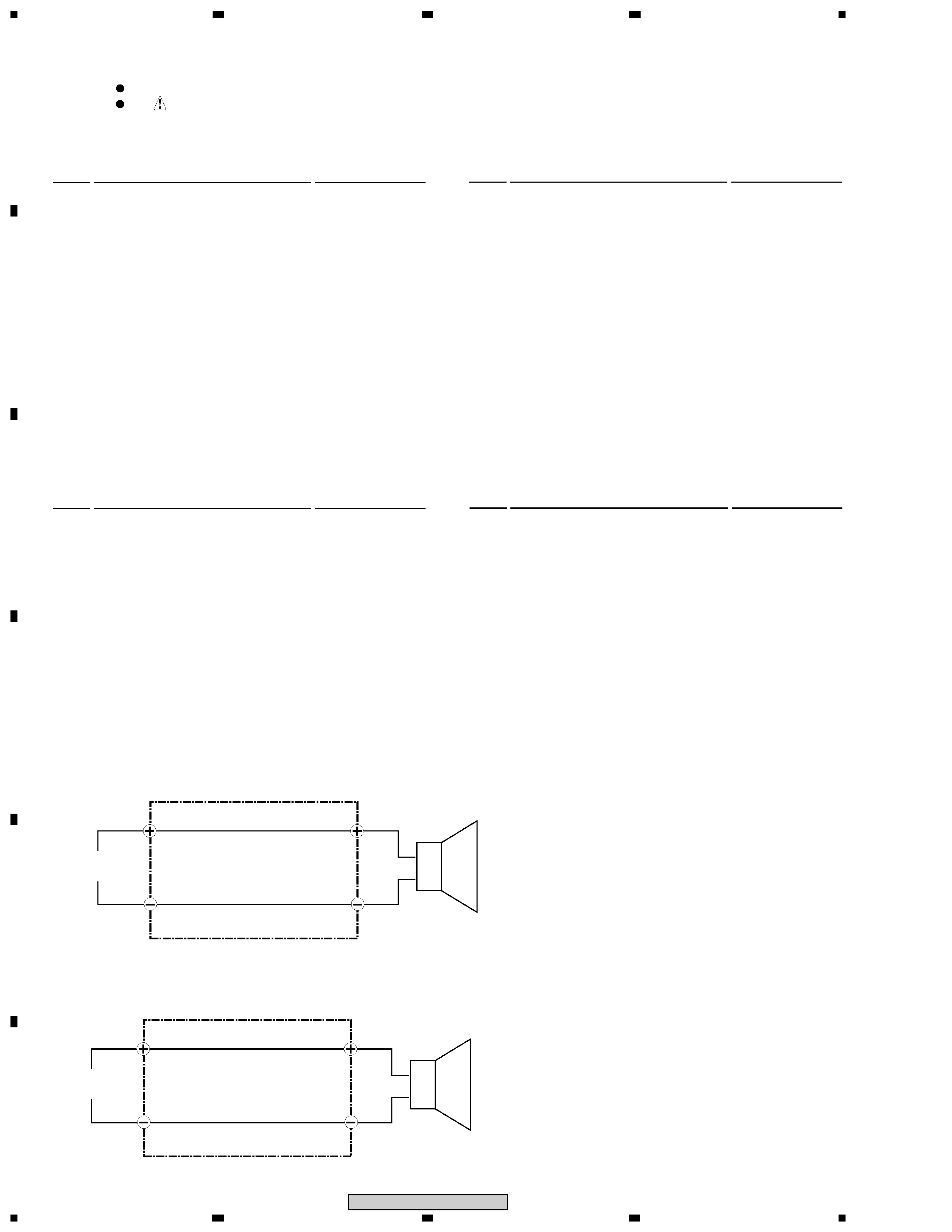
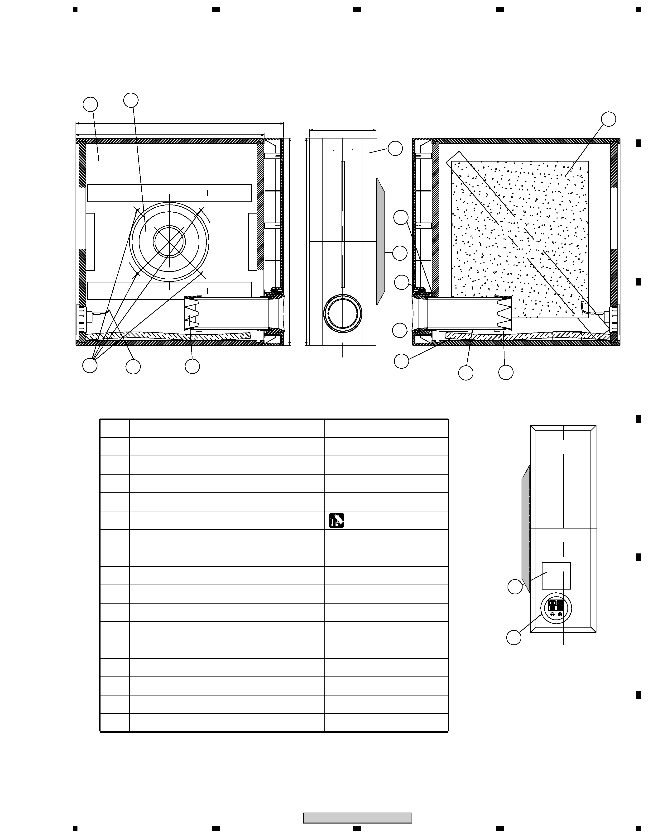
CS Assy ( Subwoofer )
The grille assy is attached to the cabinet by press-fitting with
adhesive. To detach it, pry it open by inserting a flat blade
screwdriver into backside of it. To attach it, clean the press-
fitting part and apply a bit of adhesive . Then press it to the
bafle.
The subwoofer is attached to the baffle by 4 external screws.
To detach it, unfasten those screws.
When attaching it, face its terminal upward.
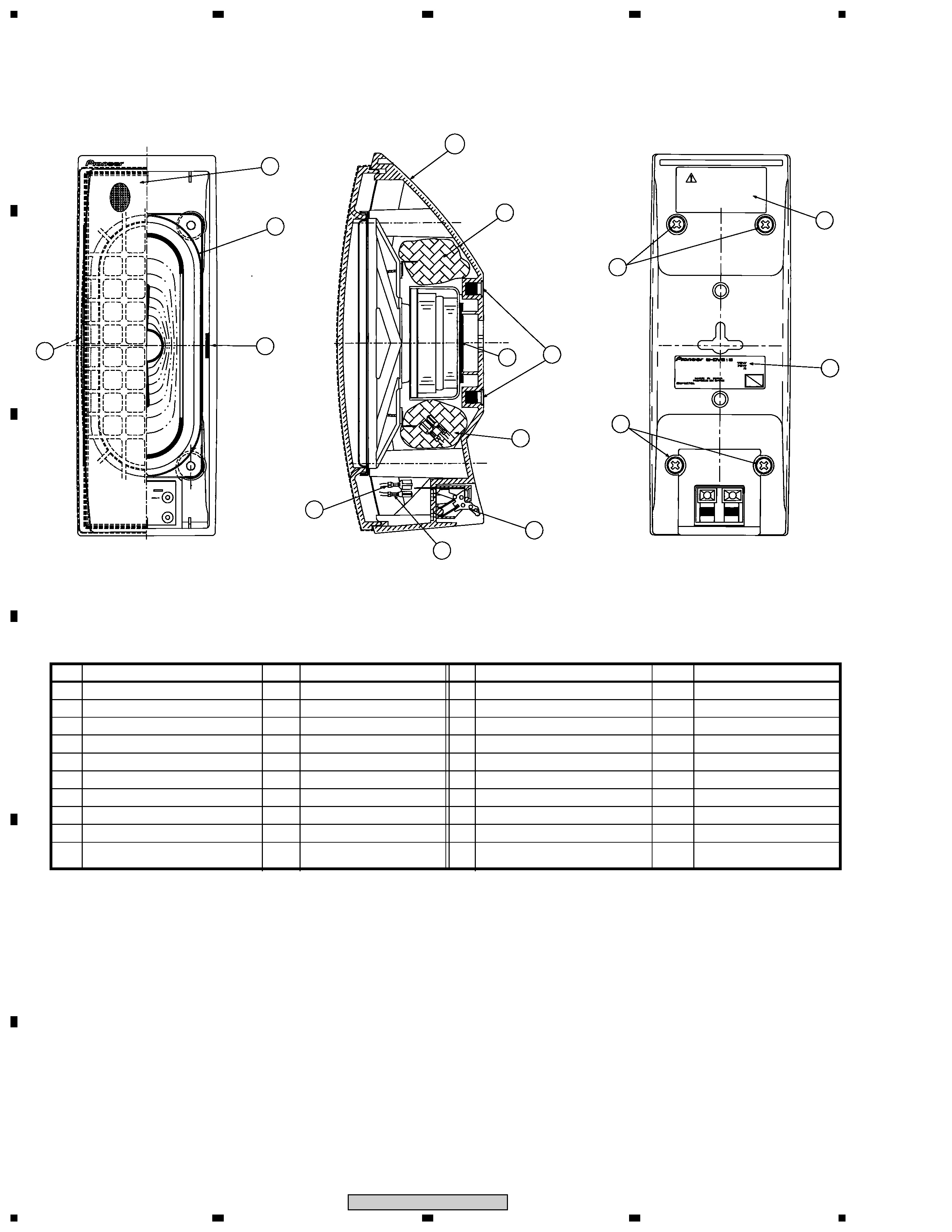
CS Assy ( Front / Surround Speaker )
The grille assy is attached to the cabinet by 4 screws. To detach
it ,unfasten those screws.
The speaker unit, together with the Grille, is atached to the
cabinet by 4 external screws.
To detach it, first unfasten those screws. Next remove the cabi-
net. Then remove the cable.
When attaching it, face its terminal toward the input terminal.
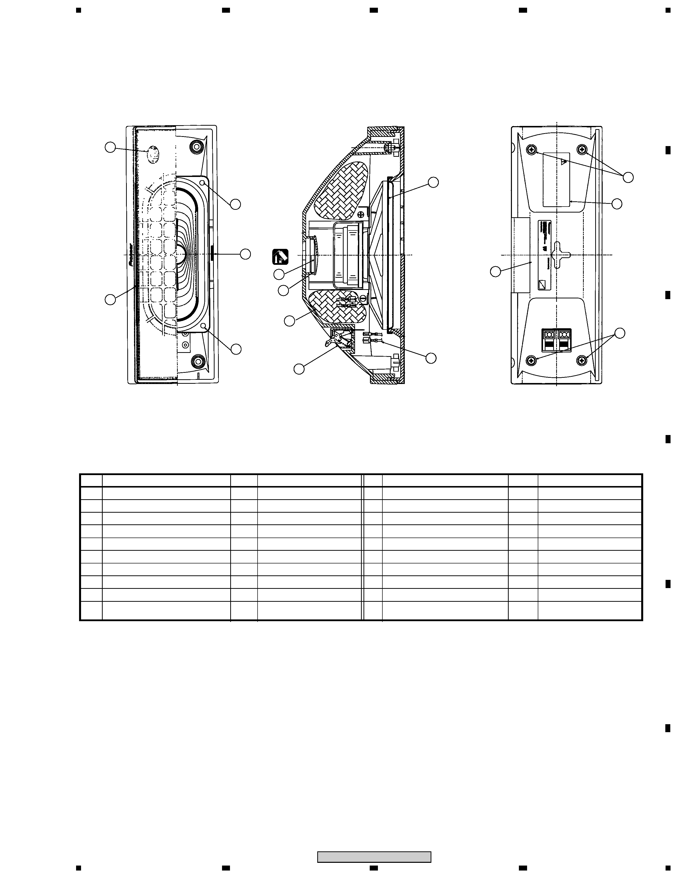
CS Assy ( Center Speaker )
The grille assy is attached to the cabinet by 4 screws. To detach
it, unfasten those screws.
The speaker unit is attached to the Grille by 4 internal screws.
To detach it, first unfasten those screws. Next remove cabinet.
Then remove the cable.
When attaching it, face its terminal toward the input terminal.
Subwoofer
Center
Front / Surround
S-DV515
XTW/EW