ORDER NO.
PIONEER CORPORATION 4-1, Meguro 1-chome, Meguro-ku, Tokyo 153-8654, Japan
PIONEER ELECTRONICS (USA) INC. P.O. Box 1760, Long Beach, CA 90801-1760, U.S.A.
PIONEER EUROPE NV Haven 1087, Keetberglaan 1, 9120 Melsele, Belgium
PIONEER ELECTRONICS ASIACENTRE PTE. LTD. 253 Alexandra Road, #04-01, Singapore 159936
PIONEER CORPORATION 2006
RRV3456
T ZZS SEPT. 2006 Printed in Japan
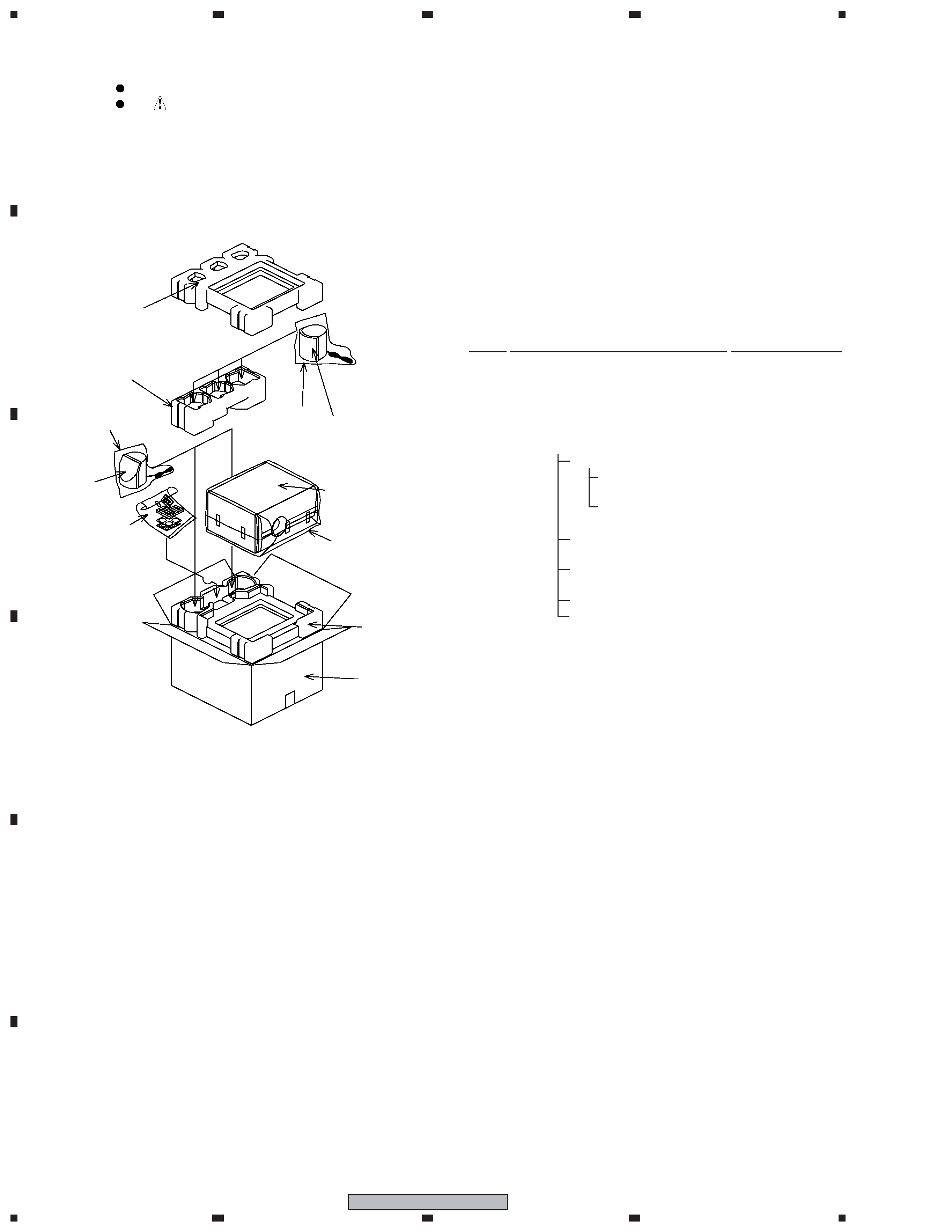
1. REASSEMBLY AND DISASSEMBLY PRECAUTIONS
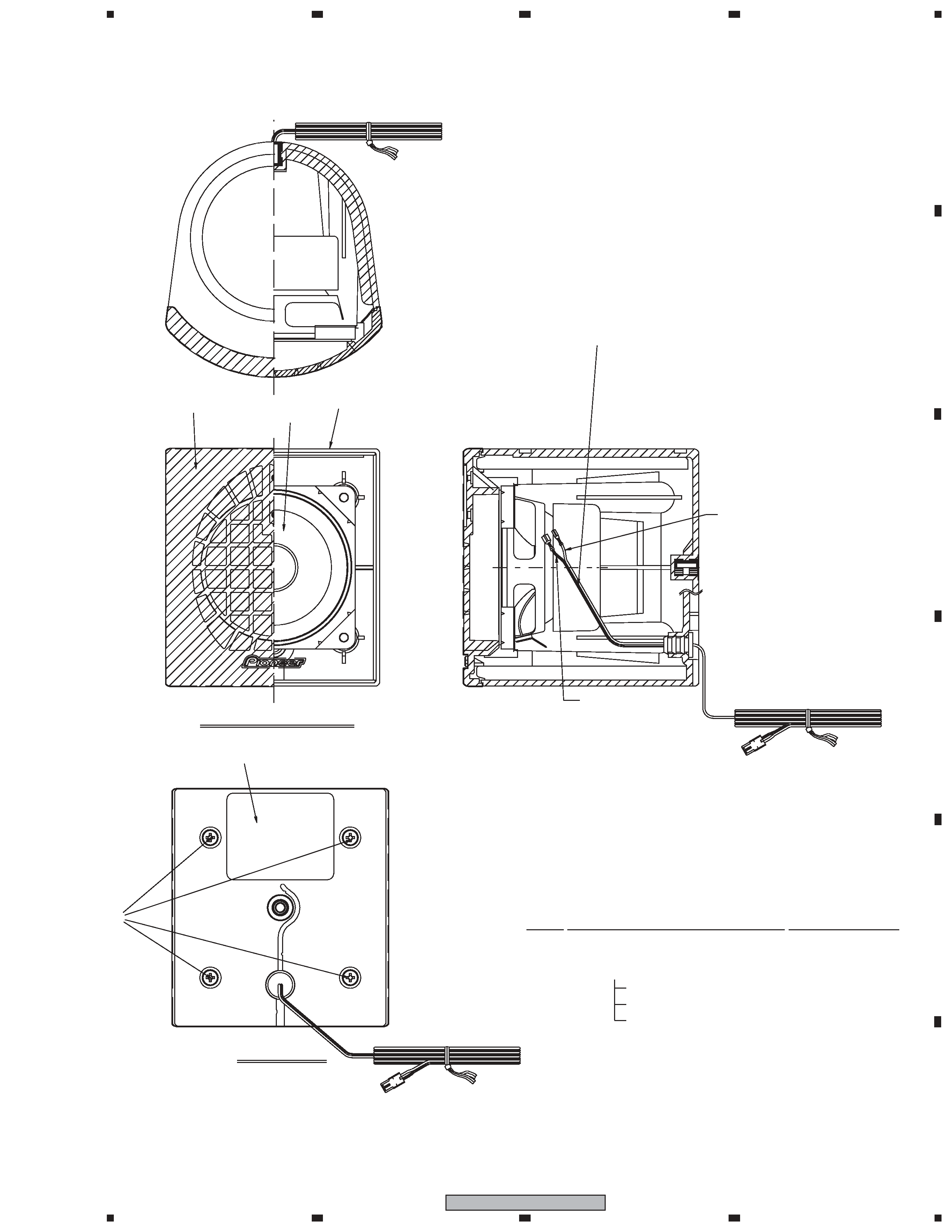
FRONT SPEAKER
The grille assy is attached to the cabinet by 4 external screws.
To detach it, unfasten those screws.
The speaker unit, together with the grille, is attached to the
cabinet by 4 external screws.
To detach it, first unfasten those screws. Next remove the cabi-
net. Then remove the cable.
When attaching it, face its terminal downward.
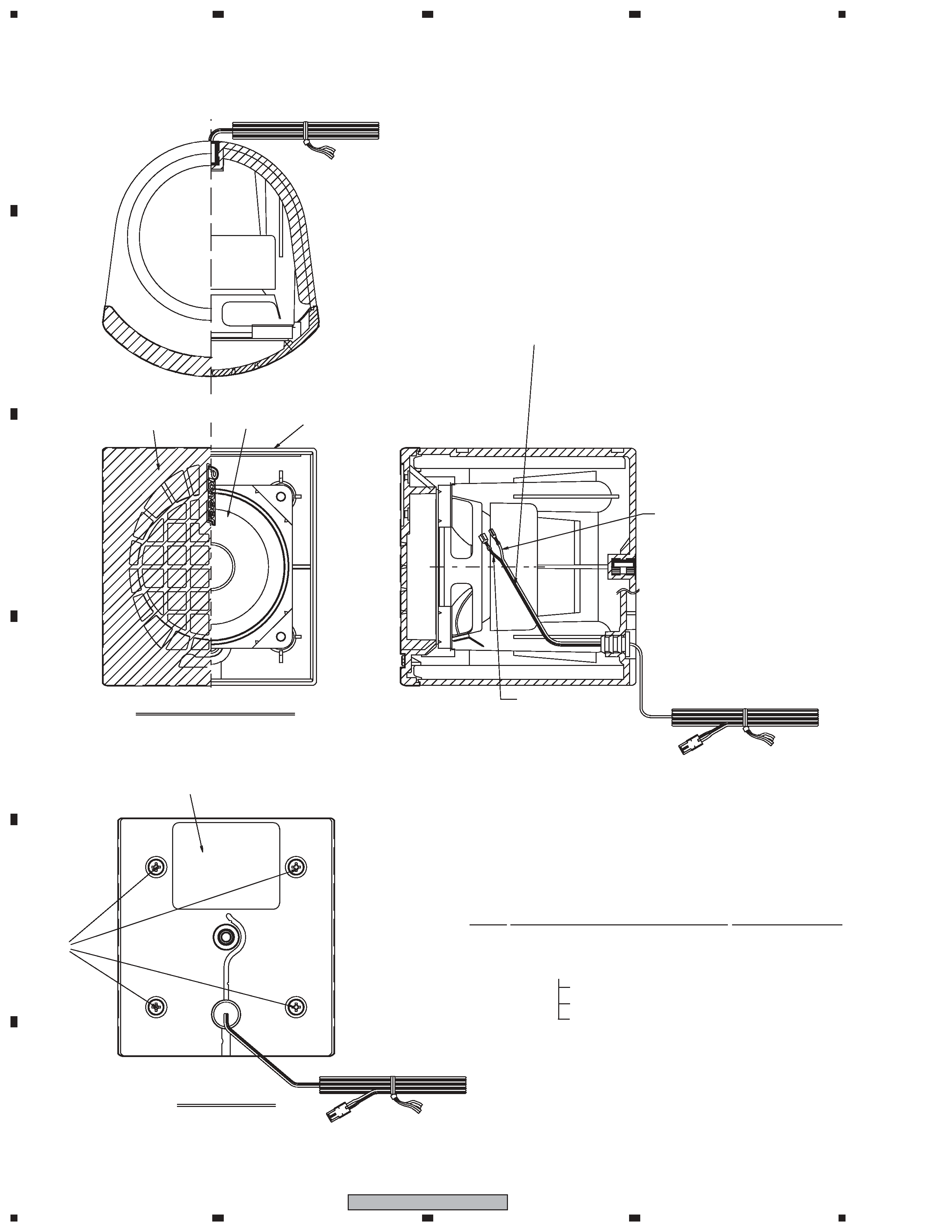
CENTER SPEAKER
The grille assy is attached to the cabinet by 4 external screws.
To detach it, unfasten those screws.
The speaker unit, together with the grille, is attached to the
cabinet by 4 external screws.
To detach it, first unfasten those screws. Next remove the cabi-
net. Then remove the cable.
When attaching it, face its terminal rightward.
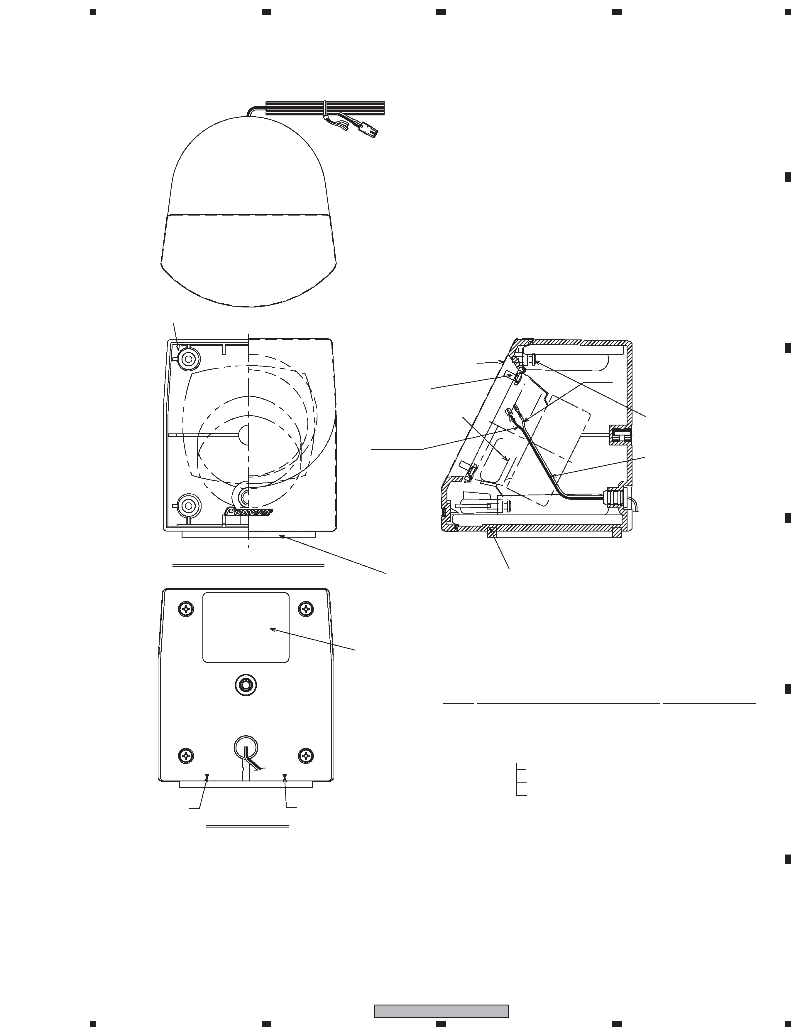
SURROUND SPEAKER
The grille assy is attached to the cabinet by 4 screws. To detach
it, unfasten those screws.
The speaker unit is attached to the grille by 4 internal screws.
To detach it, first unfasten those screws. Next remove the cable.
When attaching it, face its terminal downward.
SUBWOOFER
The speaker unit is attached to the rear baffle by 4 external
screws. To detach it, unfasten those screws.
When attaching it, face its terminal rightward.
SPEAKER SYSTEM
S-DV151
XCN5
Sub Woofer
Center
Surround
Front
This product is component of system.
Component
System
Service Manual
Remarks
DVD 5.1ch SURROUND SYSTEM
HTZ-151DV/NAXJ5
RRV3415
DVD/CD RECEIVER
XV-DV151/NAXJ5
RRV3414
SPEAKER SYSTEM
S-DV151/XCN5
RRV3456
This service manual