1
CS-G405-K/Q
Service
Manual
ORDER NO.
PET99016
PIONEER CORPORATION 4-1, Meguro 1-Chome, Meguro-ku, Tokyo 153-8654, Japan
PIONEER ELECTRONICS SERVICE, INC. P.O. Box 1760, Long Beach, CA 90801-1760, U.S.A.
PIONEER ELECTRONIC (EUROPE) N.V. Haven 1087, Keetberglaan 1 B-9120 Melsele, Belgium
PIONEER ELECTRONICS ASIACENTRE PTE. LTD. 501 Orchard Road, #10-00, Wheelock Place, Singapore 238880
©PIONEER CORPORATION 1999
1999 Printed in U.S.A.
HOW TO REASSEMBLE AND
DISASSEMBLE
65S
This service manual is intended for qualified service technicians; it is
not meant for the casual do-it- your selfer. Qualified technicians have
the necessary test equipment and tools, and have been trained to
properly and safely repair complex products such as those covered by
this manual.
Improperly performed repairs can adversely affect the safety and
reliability of the product and may void the warranty. If you are not
qualified to perform the repair of this product properly and safely, you
should not risk trying to do so and refer the repair to a qualified service
technician.
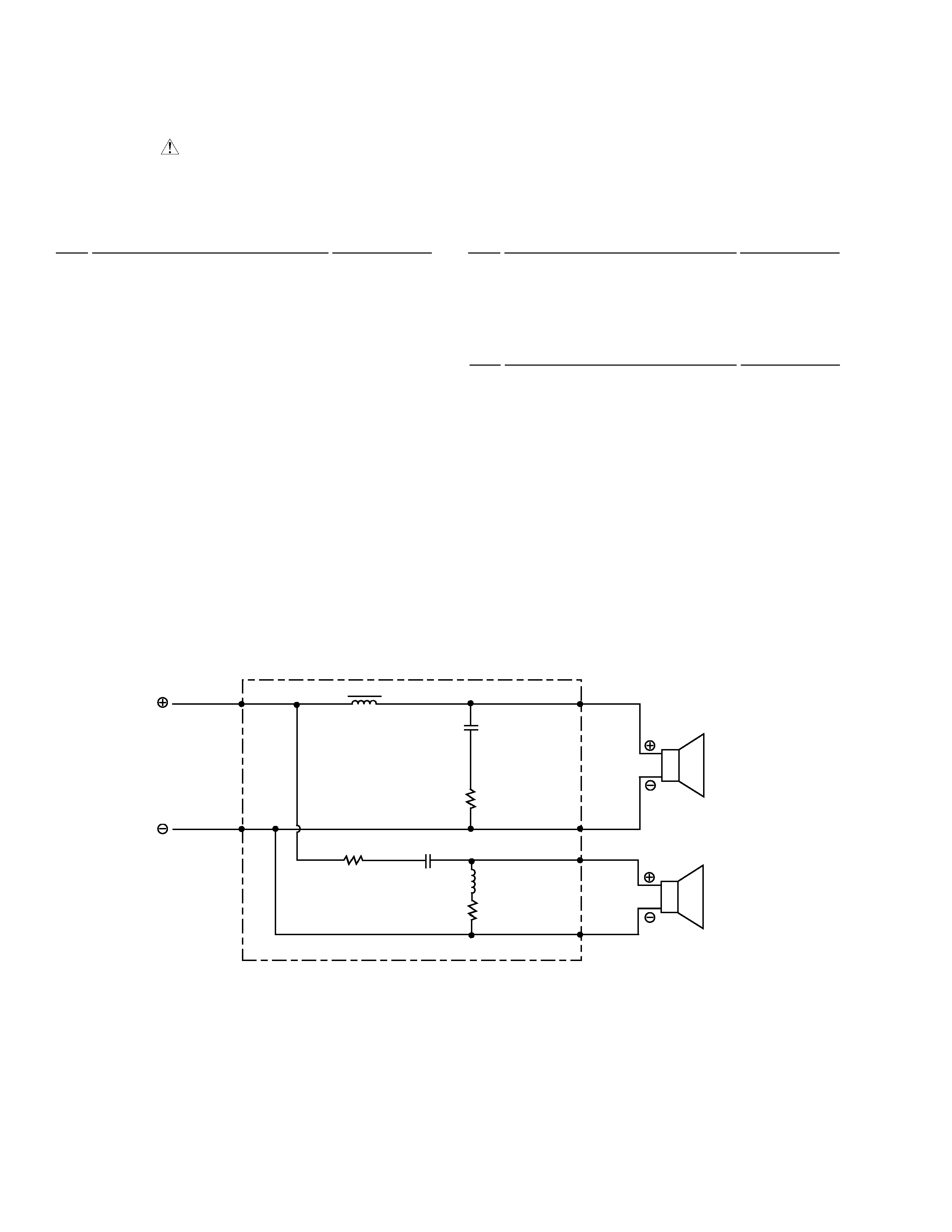
SPEAKER SYSTEM
S-DS1-H
·
The grille is attached to the trim baffle. Detach it by pulling toward
you.
·
The baffle is attached to the cabinet by screws. To detach it,
unfasten those screws..
·
The woofer is attached to the baffle by internal screws. To detach
it, unfasten those screws. When attaching, face its terminal
downward.
·
The tweeter is attached to the baffle by internal screws. To detach
it, unfasten those screws.
·
The crossover assembly is attached to the cabinet with adhesive.
To detach it, first remove terminal cup, and then remove it.