ORDER NO.
PIONEER CORPORATION 4-1, Meguro 1-chome, Meguro-ku, Tokyo 153-8654, Japan
PIONEER ELECTRONICS (USA) INC. P.O. Box 1760, Long Beach, CA 90801-1760, U.S.A.
PIONEER EUROPE NV Haven 1087, Keetberglaan 1, 9120 Melsele, Belgium
PIONEER ELECTRONICS ASIACENTRE PTE. LTD. 253 Alexandra Road, #04-01, Singapore 159936
PIONEER CORPORATION 2007
Rear
Front
Stem
(the bottom of cabinet)
Speaker Stand Base
RRV3546
T ZZA JAN. 2007 Printed in Japan
SPEAKER SYSTEM
S-CH200
XCN5
GRILLE
The grille is attached to the cabinet by its bosses applied with adhe-
sive. To detach it, pry it open by inserting a flat blade screwdriver
into lower right and lower left slot. To attach it, apply adhesive to
the holes on the baffle. Then press it to the baffle.
CAUTION
There are 10 bosses for press-fitting at the grille. To detach the
grille, remove in order from lower bosses. (Refer to the figure in
page 3.) In order not to damage the bosses, don't remove it
forcibly. Pry it open little by little. Be sure to insert a flat blade
screwdriver from just beside of its bosses.
WOOFER
The woofer is attached to the baffle by 4 external screws.
To detach it, unfasten those screws. To detach it, first remove the
grille. Then remove the screws. When attaching it, face its terminal
downward.
TWEETER
The tweeter is attached to the baffle by 3 external screws. To detach
it, unfasten those screws. To detach it, first remove the grille. Then
remove the screws. When attaching it, face its terminal leftward
and rightward.
COSMETIC PANEL
The cosmetic panel is attached to the baffle by its bosses. To detach
it, pry it open by inserting a flat blade screwdriver into lower slot.
To detach it, first remove the speaker stand base and grille. Then
remove the cosmetic panel. When attaching it, fit the boss into the
hole on the baffle.
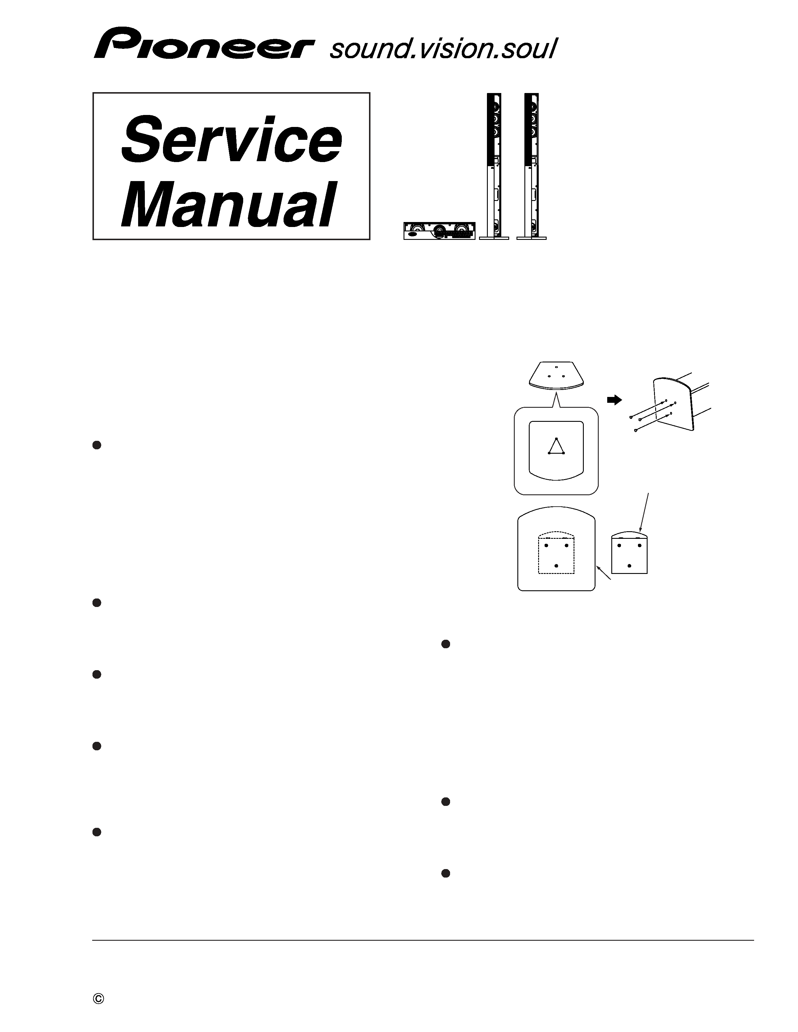
SPEAKER STAND BASES
The speaker stand base is attached to the bottom of cabinet by 3
external screws. To detach it, unfasten those screws.Attach the
speaker stand bases to the stems using the screws provided. Once
you have aligned the stem and base, secure with the small screws at
the points shown following diagram. Note that the speaker should
face in the direction of the base of the isosceles triangle (outlined
below).
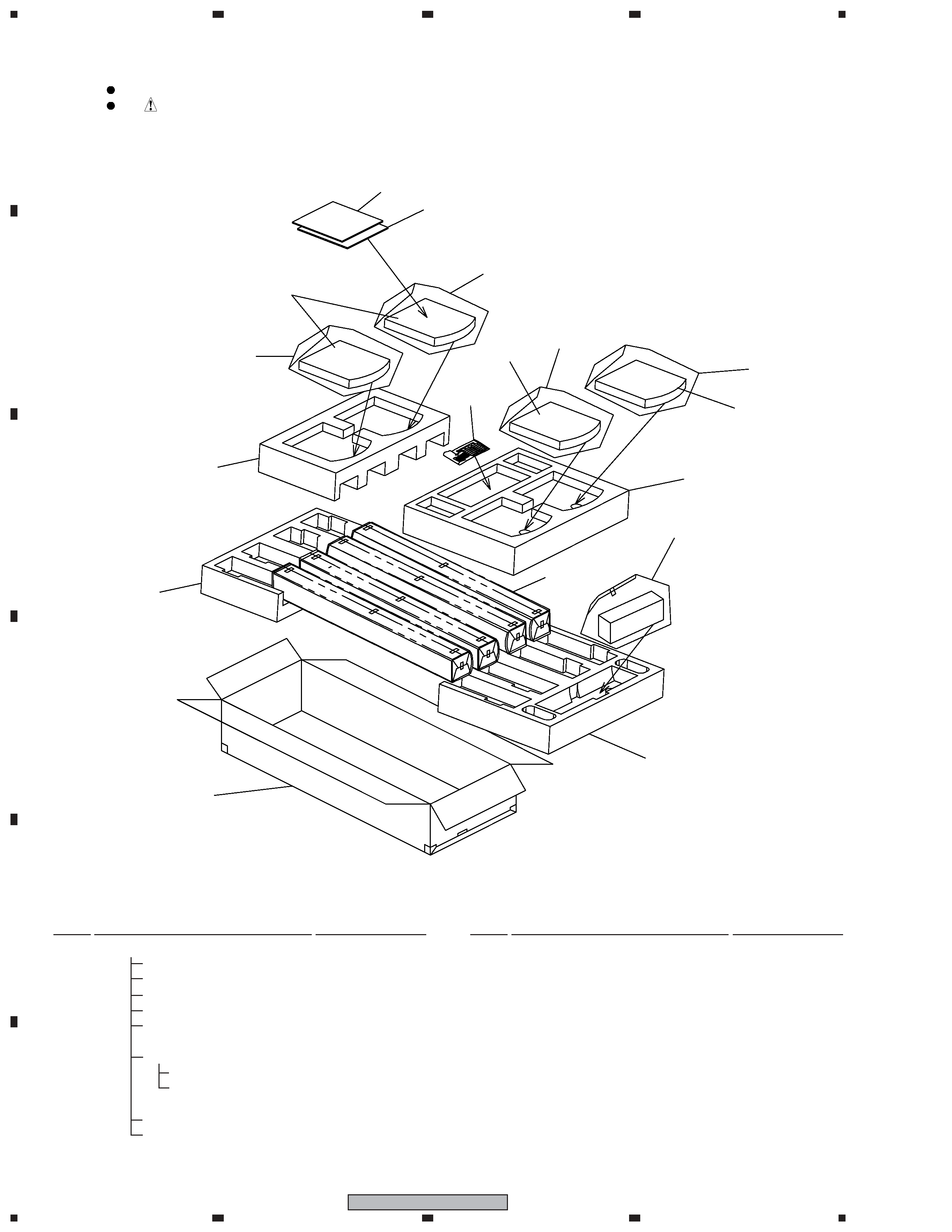
1. REASSEMBLY AND DISASSEMBLY
PRECAUTIONS
1.1
FRONT, SURROUND SPEAKER
1.2
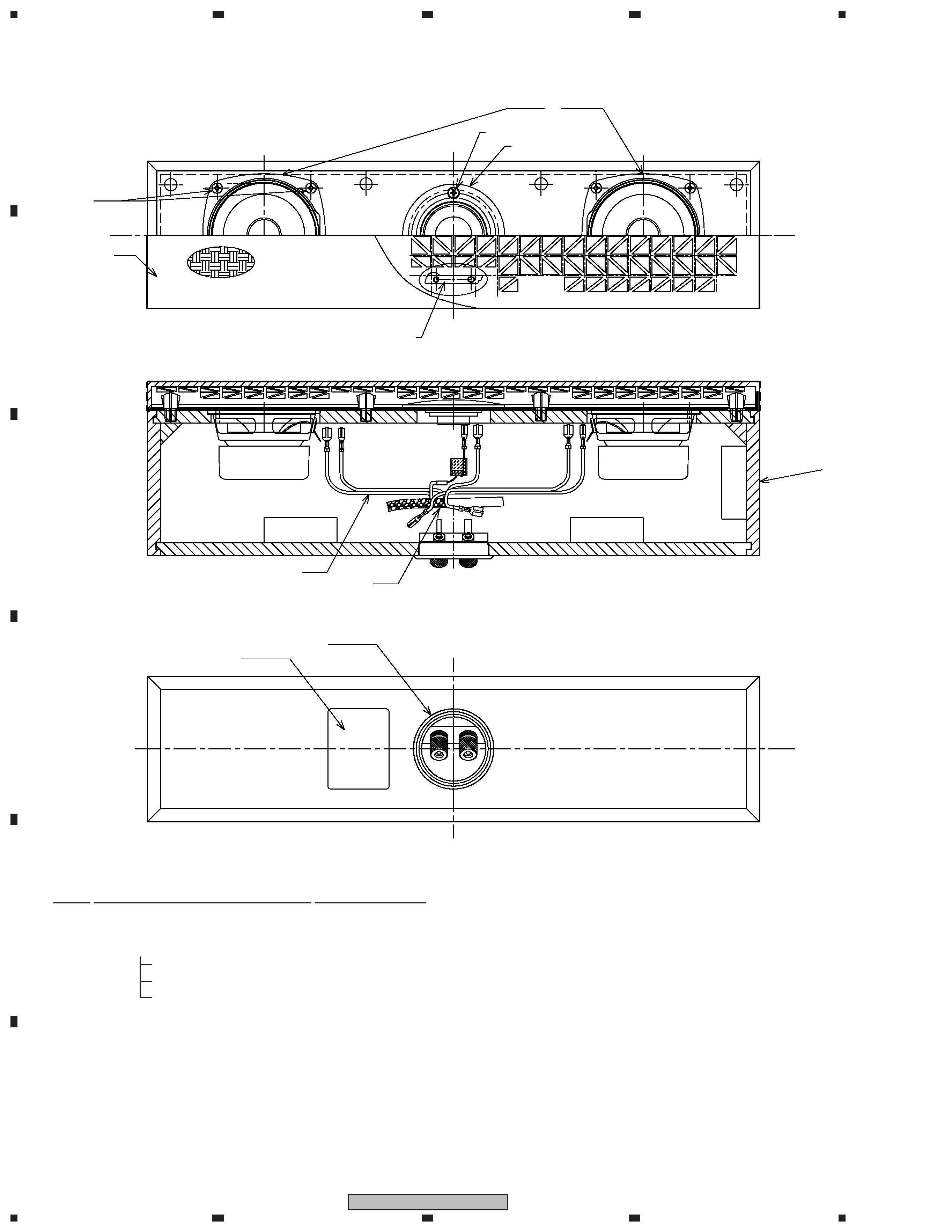
CENTER SPEAKER
S-CH200
GRILLE
The grille is attached to the cabinet by its bosses applied with adhe-
sive. To detach it, pry it open by inserting a flat blade screwdriver
into lower right and lower left slot. To attach it, apply adhesive to
the holes on the baffle. Then press it to the baffle.
CAUTION
There are 8 bosses for press-fitting at the grille. To detach the
grille, remove in order from lower bosses. (Refer to the figure in
page 3.) In order not to damage the bosses, don't remove it
forcibly. Pry it open little by little. Be sure to insert a flat blade
screwdriver from just beside of its bosses.
WOOFER
The woofer is attached to the baffle by 4 external screws.
To detach it, unfasten those screws. To detach it, first remove the
grille. Then remove the screws. When attaching it, face its terminal
downward.
TWEETER
The tweeter is attached to the baffle by 3 external screws. To detach
it, unfasten those screws. To detach it, first remove the grille. Then
remove the screws. When attaching it, face its terminal leftward
and rightward.
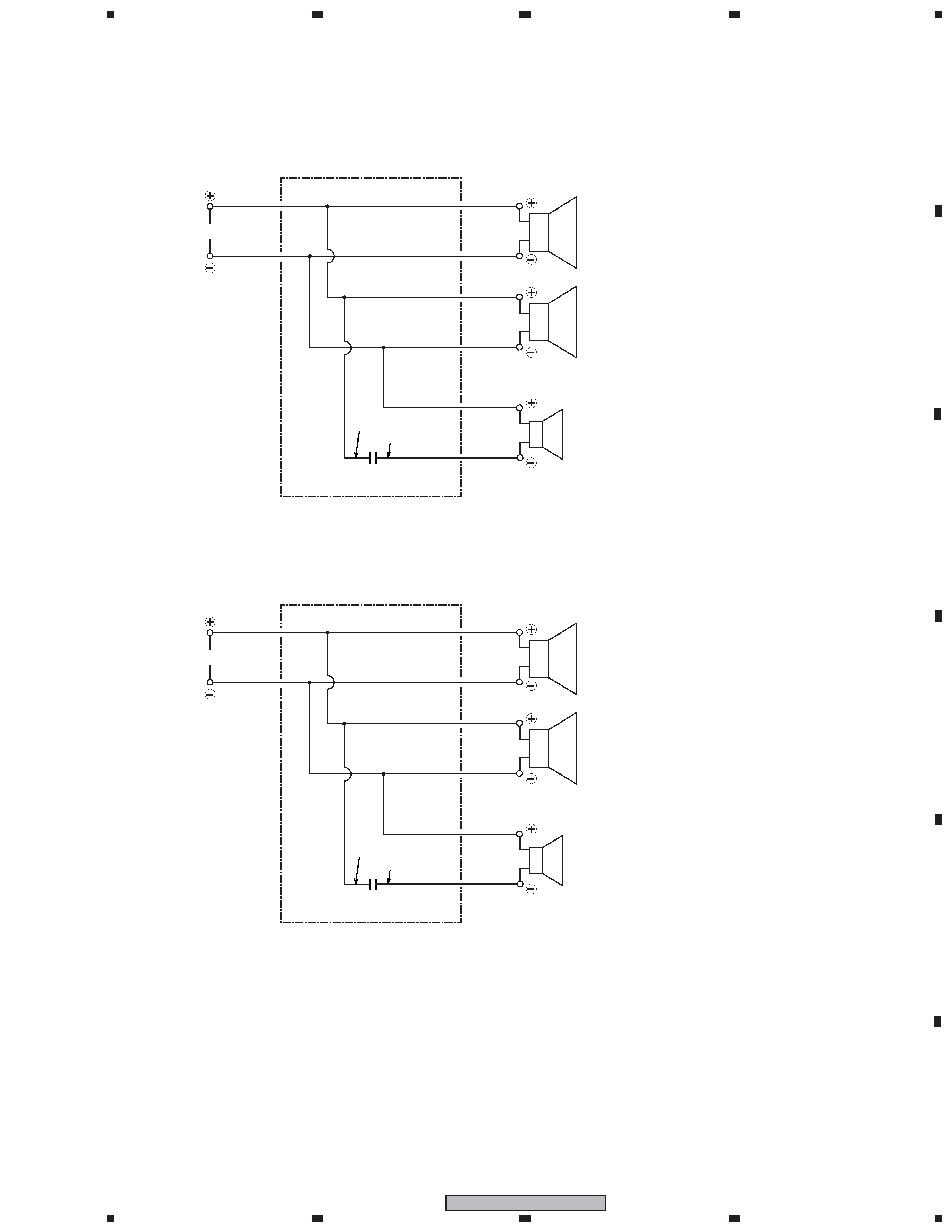
Front Surround
Center