ORDER NO.
PIONEER CORPORATION 4-1, Meguro 1-chome, Meguro-ku, Tokyo 153-8654, Japan
PIONEER ELECTRONICS SERVICE, INC. P.O. Box 1760, Long Beach, CA 90801-1760, U.S.A.
PIONEER EUROPE NV Haven 1087, Keetberglaan 1, 9120 Melsele, Belgium
PIONEER ELECTRONICS ASIACENTRE PTE. LTD. 253 Alexandra Road, #04-01, Singapore 159936
PIONEER CORPORATION 2000
RRV2391
T-ZZM SEPT. 2000 Printed in Japan
FOR PRECAUTION OF
REASSEMBLY AND DISASSEMBLY
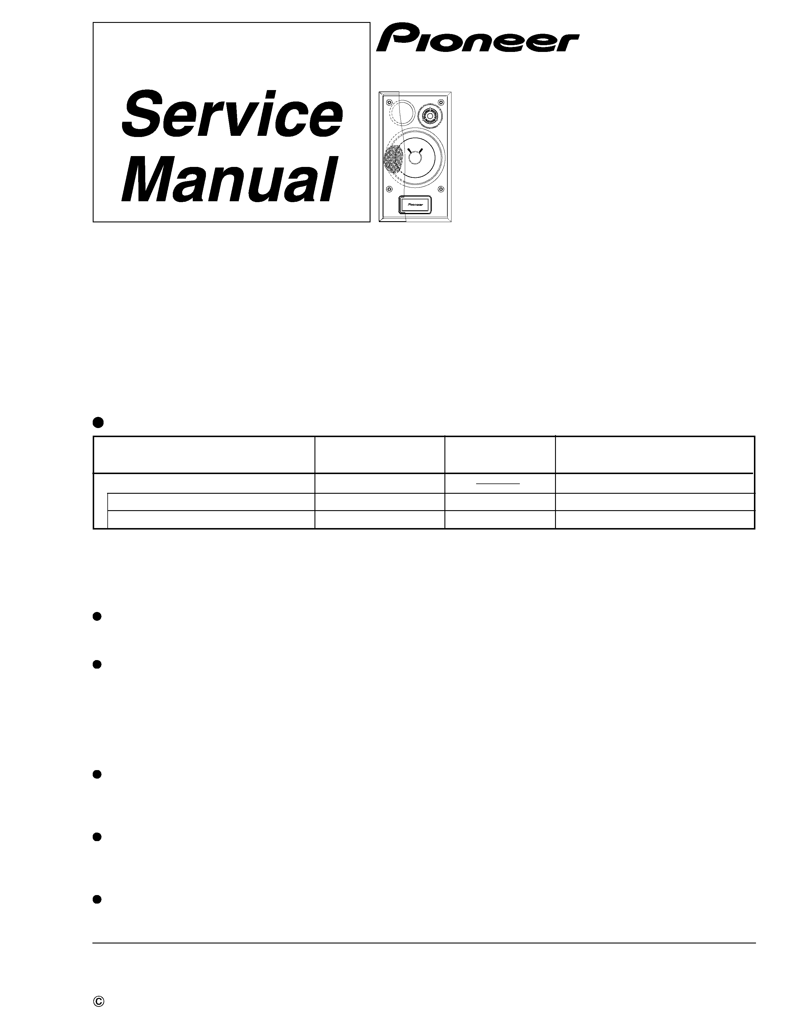
S-C3-S-LR
XMD/JP
SPEAKER SYSTEM
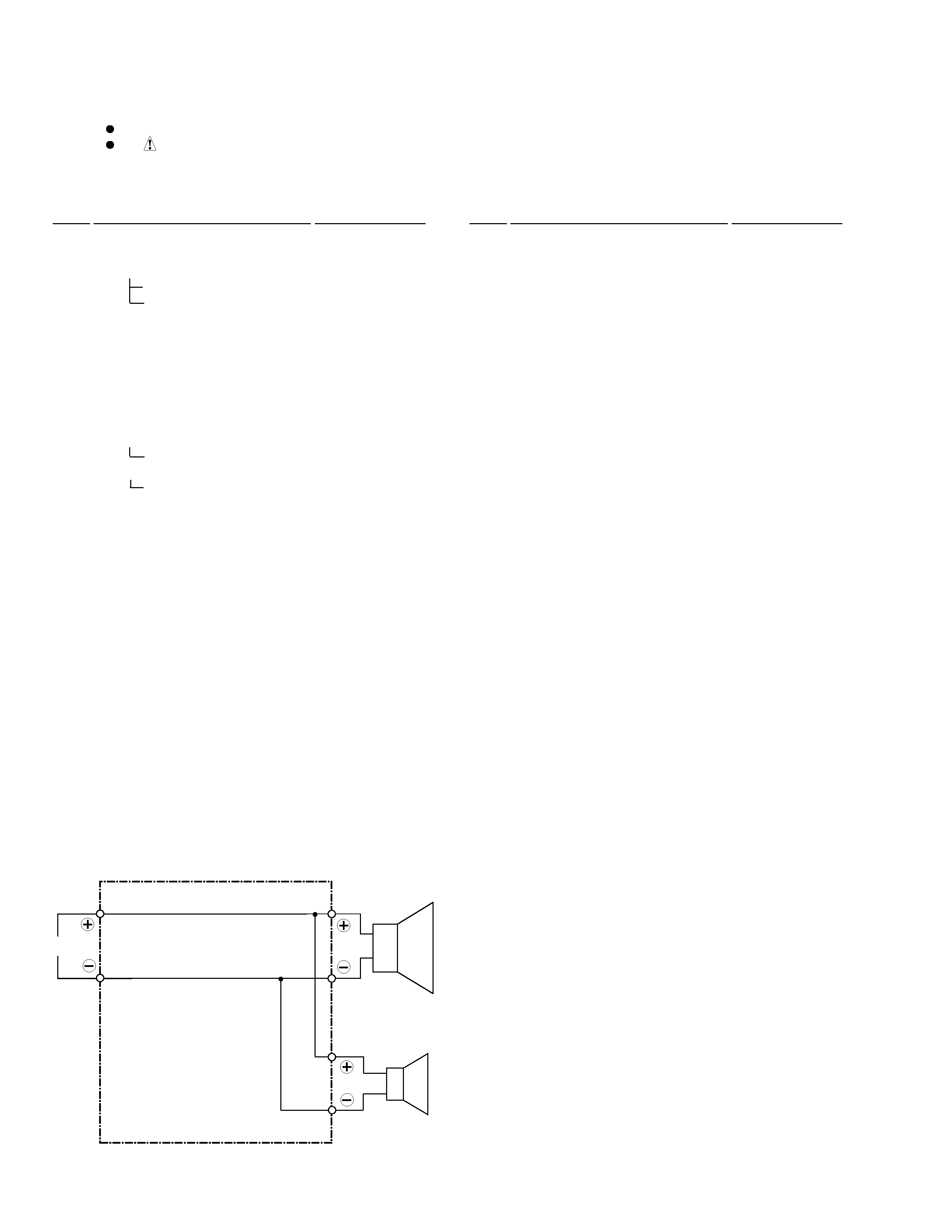
This product is component of system.
System
Service Manual
Remarks
RRV2384
RRV2391
Component
X-MDX717
XR-MDX717
S-C3-S-LR
COMPACT MINI COMPONENT
STEREO CD/MD RECIEVER
SPEAKER SYSTEM
This service manual
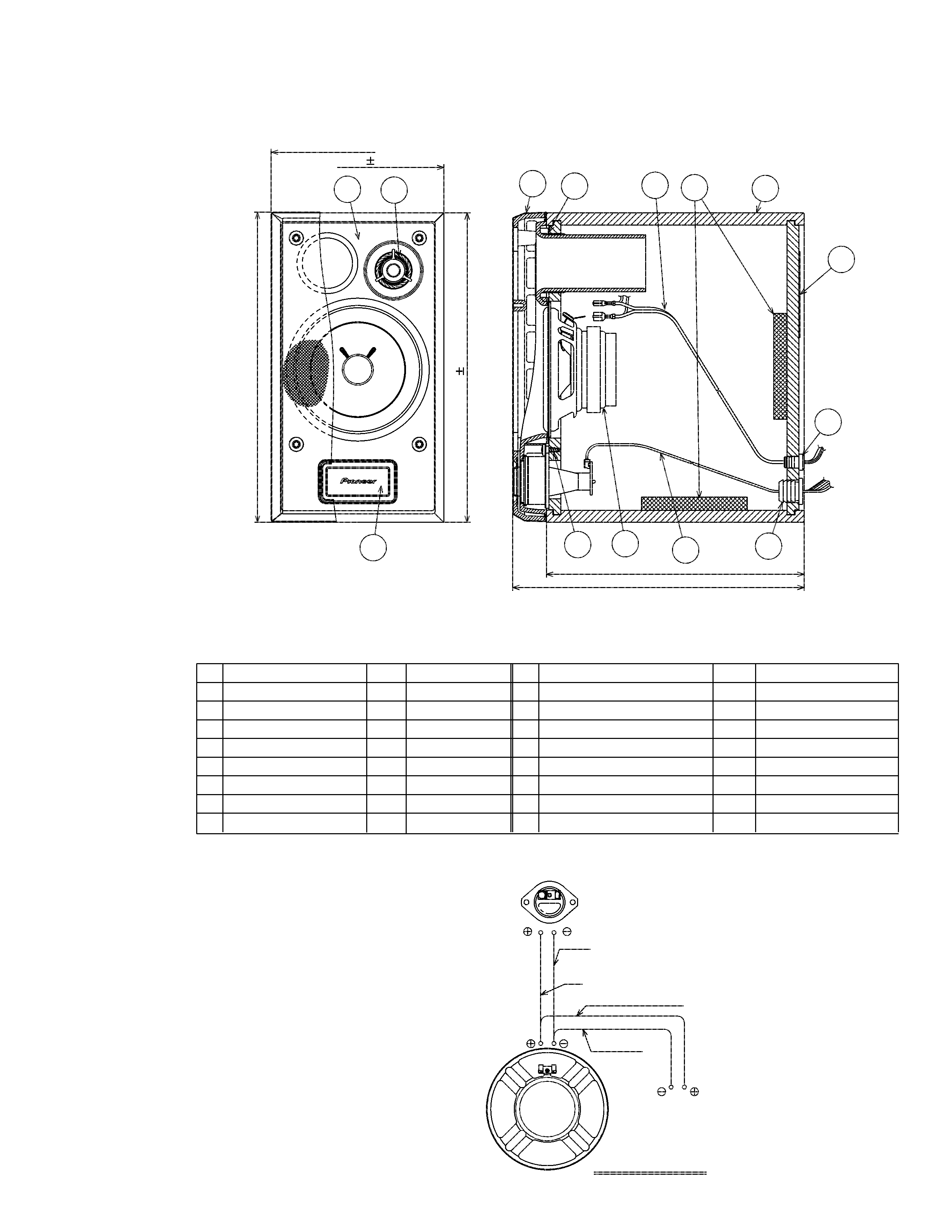
The grille is attached to the cabinet by catches. Detach by pull-
ing it toward you.
The woofer is attached to the baffle by 4 external screws.
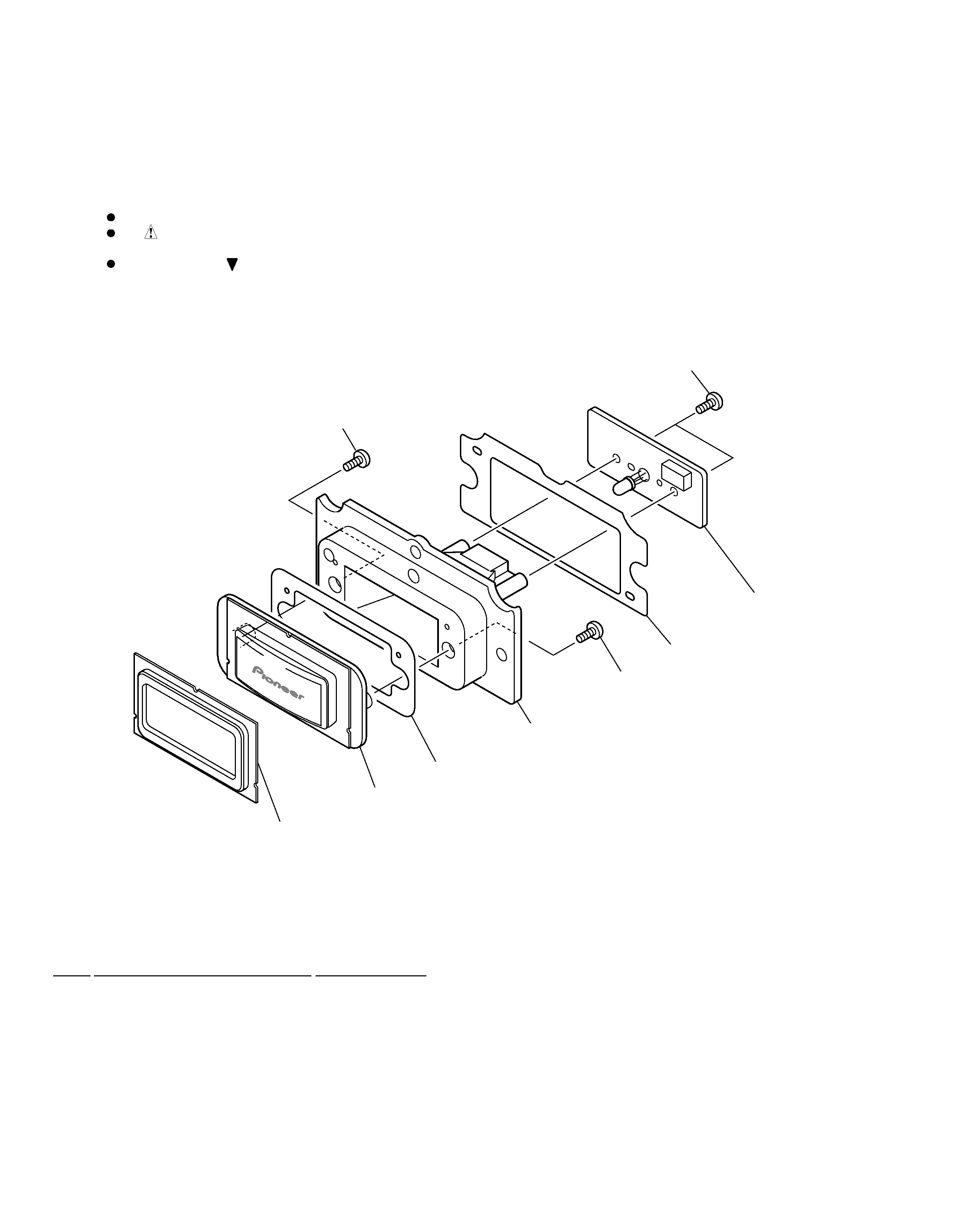
The cosmetic baffle is attached to the baffle by 4 external
screws. To unfasten those screws, detach 4 catches inserted to
holes on the cosmetic baffle. To detach the cosmetic baffle,
unfasten those screws. When attaching the woofer, face its ter-
minal upward.
The Tweeter is attached to the baffle by 2 external screws. To
detach it, unfasten those screws. When attaching it, face its ter-
minal downward.
The LED box assy is attached to the baffle by 3 external screws.
To detach it, unfasten those screws. When attaching it, fit the
boss of the LED box assy into the hollow on the baffle.
The cord stopper is attached to the back board by press-fitting.
To detach it, pull it while rotating it by the radio pincers