S-A790VLR
2
FOR PRECAUTION OF
REASSEMBLY AND DISASSEMBLY
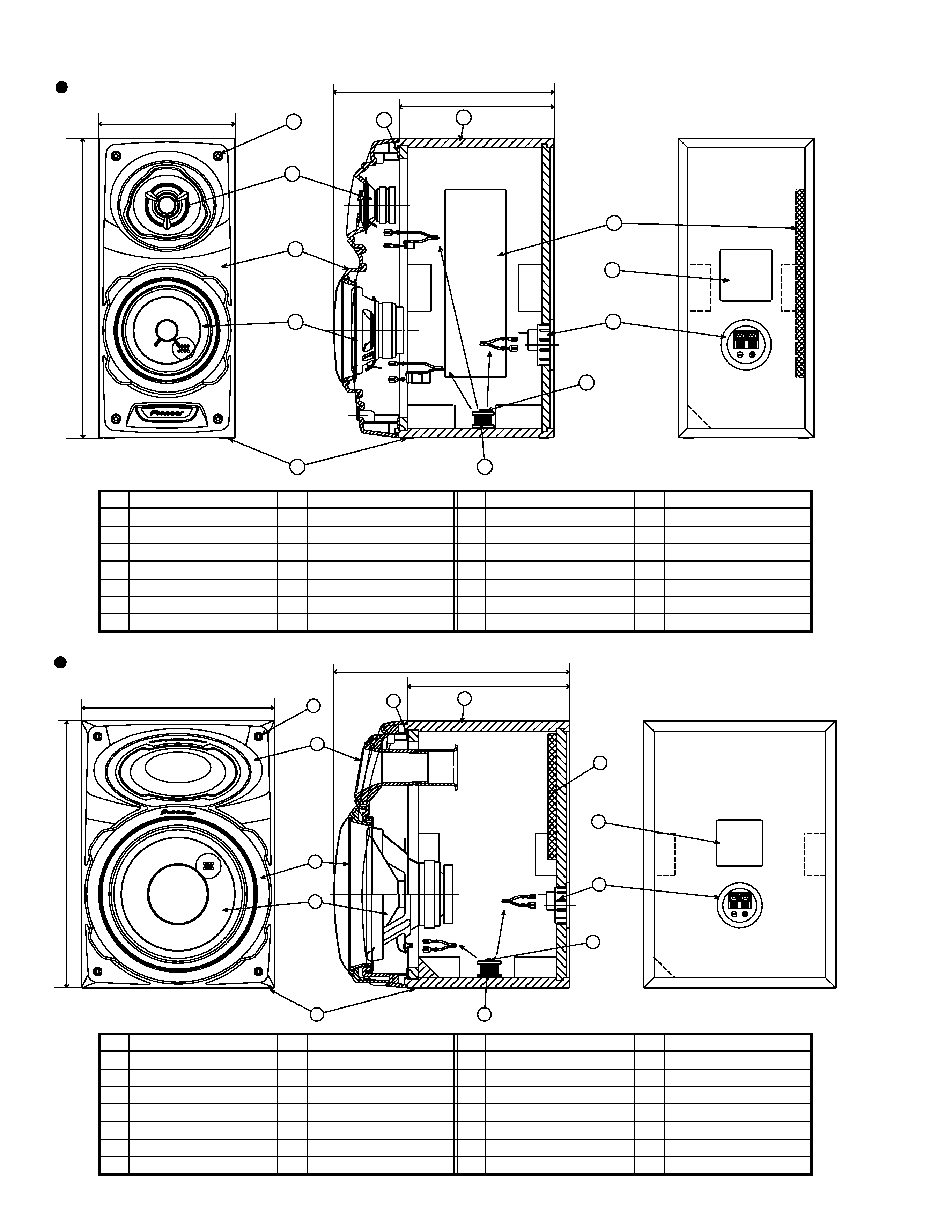
The cosmetic baffle assy is attached to the cabinet by 4 external
hexagon socket screws. To detach the cosmetic baffle assy,
loosen these screws by the hexagon screw driver. Then care-
fully disconnect the wires of the mid-range and the tweeter
mounted on the cosmetic baffle assy. To attach the cosmetic
baffle assy, replace it on the cabinet correctly and secure with
4 screws.
The mid-range is attached to the cosmetic baffle assy by 4 inter-
nal screws. To detach it, unfasten those screws. When attaching
it, face its terminal downward.
The tweeter is attached to the cosmetic baffle assy by 2 internal
screws. To detach it, unfasten those screws. When attaching it,
face its terminal downward.
The network assy is attached to the bottom board by one internal
screw and adhesive. To detach it, unfasten that screw and pry it
out.To attach it, apply adhesive to the bottom board. Then press
it to the bottom board, and secure with one screw.When attach-
ing the network assy, do it carefully so that each wire is not
touched.
( for Front Speaker)
( for Super Woofer)
The cosmetic baffle assy is attached to the cabinet by 4 external
hexagon socket screws. To detach the cosmetic baffle assy,
loosen these screws by the hexagon screw driver. Then care-
fully disconnect the wires of the woofer mounted on the cos-
metic baffle assy. To attach the cosmetic baffle assy, replace it
on the cabinet correctly and secure with 4 screws.
The woofer is attached to the cosmetic baffle assy together with
the cosmetic ring assy by 4 internal screws. To detach the
woofer (cosmetic ring assy), loosen these screws. To attach the
cosmetic ring assy, fit the notch of the cosmetic ring to the pro-
jection of the cosmetic baffle assy. To attach the woofer, face
its terminal downward. To attach the cosmetic ring assy and
woofer, replace it on the cosmetic baffle assy correctly and se-
cure with 4 screws.
The network assy is attached to the bottom board by one inter-
nal screw and adhesive. To detach it, unfasten that screw and
pry it out. To attach it, apply adhesive to the bottom board.
Then press it to the bottom board, and secure with one screw.
When attaching the network assy, do it carefully so that each
wire is not touched.
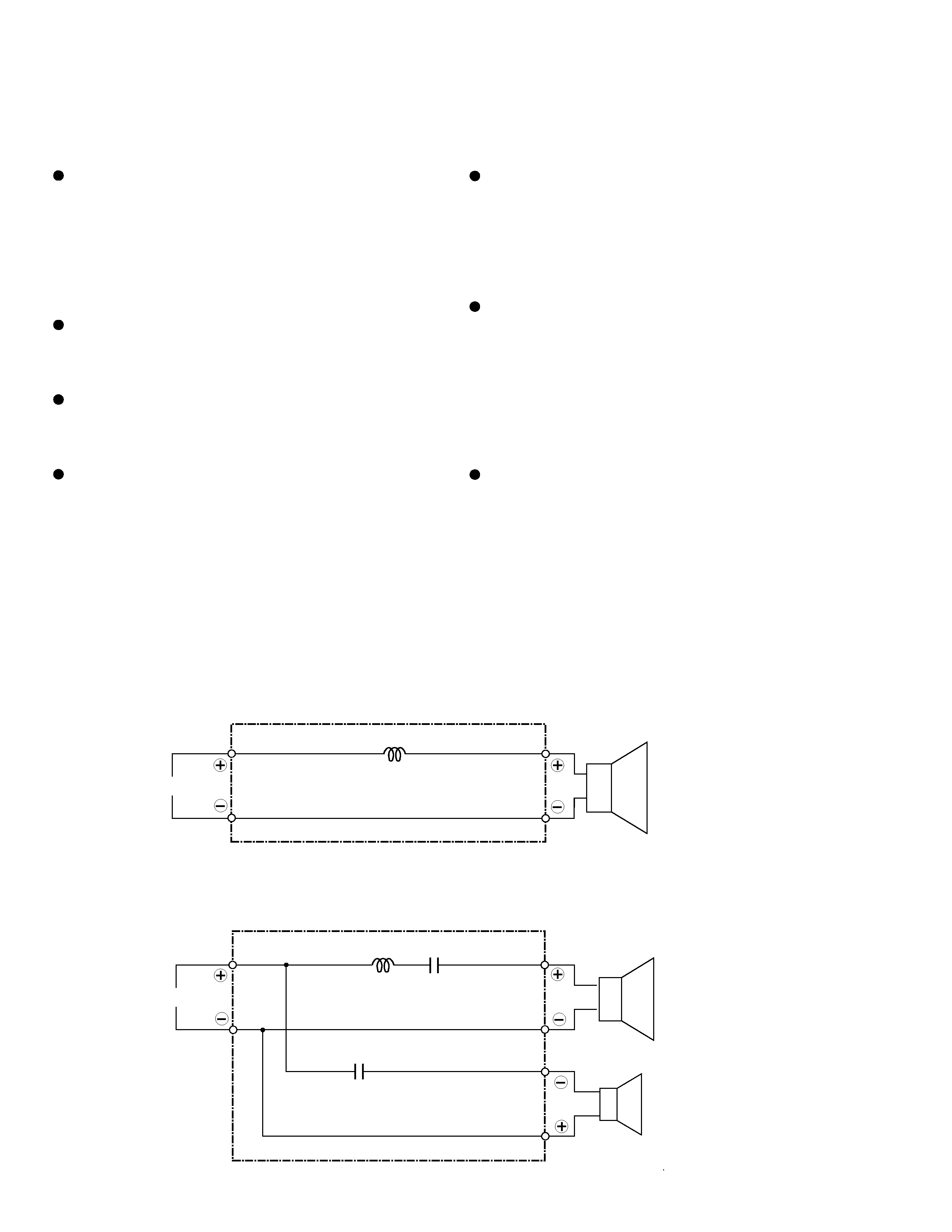
SCHEMATIC DIAGRAM
I N
Red
Blue
1.2mH
0.39mH
1.8
µF
Black
Red
Black
White
Green
White
White
Red
Network ASSY (SWN1654)
Network ASSY (SWN1680)
Super
Woofer
Mid
Tweeter
I N
82
µF