ORDER NO.
PIONEER ELECTRONIC CORPORATION 4-1, Meguro 1-Chome, Meguro-ku, Tokyo 153-8654, Japan
PIONEER ELECTRONICS SERVICE, INC. P.O. Box 1760, Long Beach, CA 90801-1760, U.S.A.
PIONEER ELECTRONIC (EUROPE) N.V. Haven 1087, Keetberglaan 1, 9120 Melsele, Belgium
PIONEER ELECTRONICS ASIACENTRE PTE. LTD. 253 Alexandra Road, #04-01, Singapore 159936
PIONEER ELECTRONIC CORPORATION 1998
RRV2037
T-ZZW NOV. 1998 Printed in Japan
FOR PRECAUTION OF
REASSEMBLY AND DISASSEMBLY
SPEAKER SYSTEM
S-A770V
XTL/NC
This product is component of system.
For the operating instructions, refer to the service manual RRV2008 for XR-A770.
The cosmetic baffle assy is attached to the cabinet by 4 external
screws. To detach the cosmetic baffle assy, loosen these
screws. Then carefully disconnect the wires of the woofer,
mid-range and tweeter mounted on the cosmetic baffle assy. To
attach the cosmetic baffle assy, replace it on the cabinet cor-
rectly and secure with 4 screws.
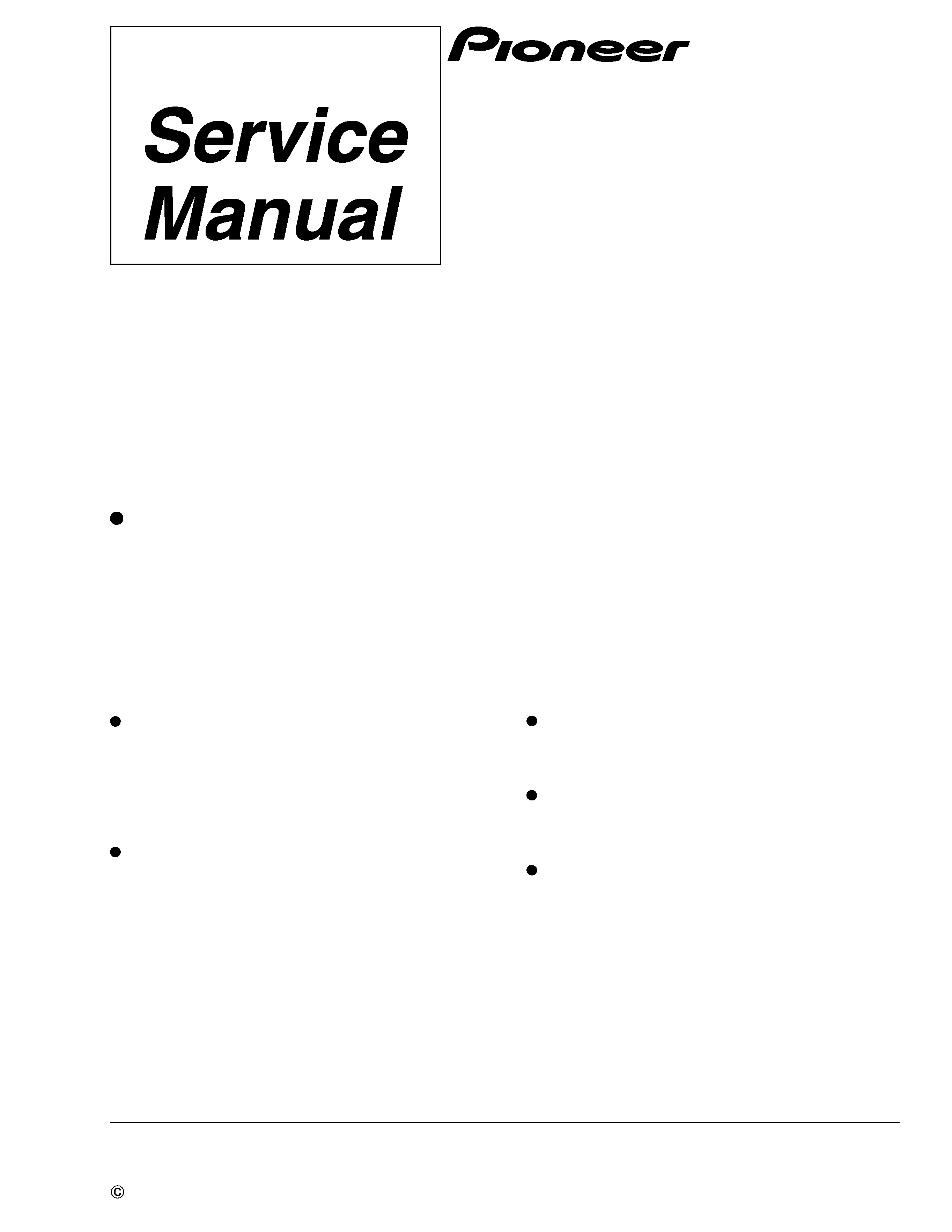
The woofer is attached to the cosmetic baffle assy together with
the woofer ring assy by 4 internal screws. To detach the woofer
(woofer ring assy), loosen these screws. To attach the woofer
ring assy, fit the boss of the woofer ring to the hollow of the
cosmetic baffle assy. To attach the woofer, face its terminal up-
ward, and fit the boss of the cosmetic baffle to the hollow of the
flame. To attach the woofer ring assy and the woofer, replace it
on the cosmetic baffle assy correctly and secure with 4 screws.
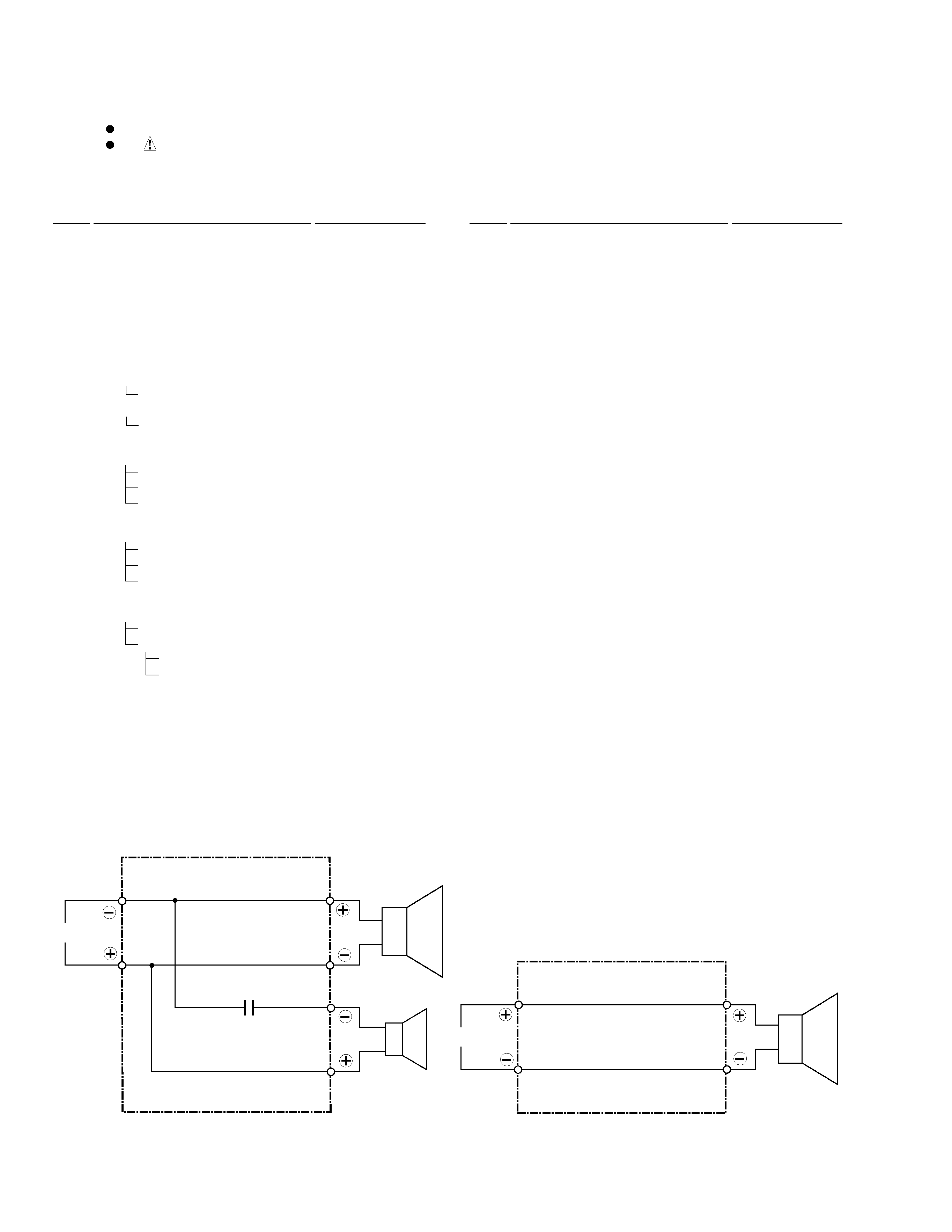
The mid-range is attached to the cosmetic baffle by 3 internal
screws. To detach it, unfasten those screws. When attaching it,
face its terminal downward.
The tweeter is attached to the cosmetic baffle by 2 internal
screws. To detach it, unfasten those screws. When attaching it,
face its terminal downward.
The network assy is attached to the back board of the cabinet
by press-fitting. To detach the network assy, strike the cord-
stopper of the network assy with a hammer from inside of the
cabinet. To attach the network assy, replace it on the back
board of the cabinet correctly by press-fitting.