ORDER NO.
PIONEER CORPORATION 4-1, Meguro 1-chome, Meguro-ku, Tokyo 153-8654, Japan
PIONEER ELECTRONICS SERVICE, INC. P.O. Box 1760, Long Beach, CA 90801-1760, U.S.A.
PIONEER ELECTRONIC (EUROPE) N.V. Haven 1087, Keetberglaan 1, 9120 Melsele, Belgium
PIONEER ELECTRONICS ASIACENTRE PTE. LTD. 253 Alexandra Road, #04-01, Singapore 159936
PIONEER CORPORATION 1999
RRV2210
T-ZZM SEPT. 1999 Printed in Japan
SPEAKER SYSTEM
S-A670
XTL/NC
This product is component of system.
System
Service Manual
Remarks
RRV2215
RRV2210
Component
X-A670
XR-A670
S-A670
STEREO CD CASSETTE DECK RECIEVER
SPEAKER SYSTEM
This service manual
FOR PRECAUTION OF
REASSEMBLY AND DISASSEMBLY
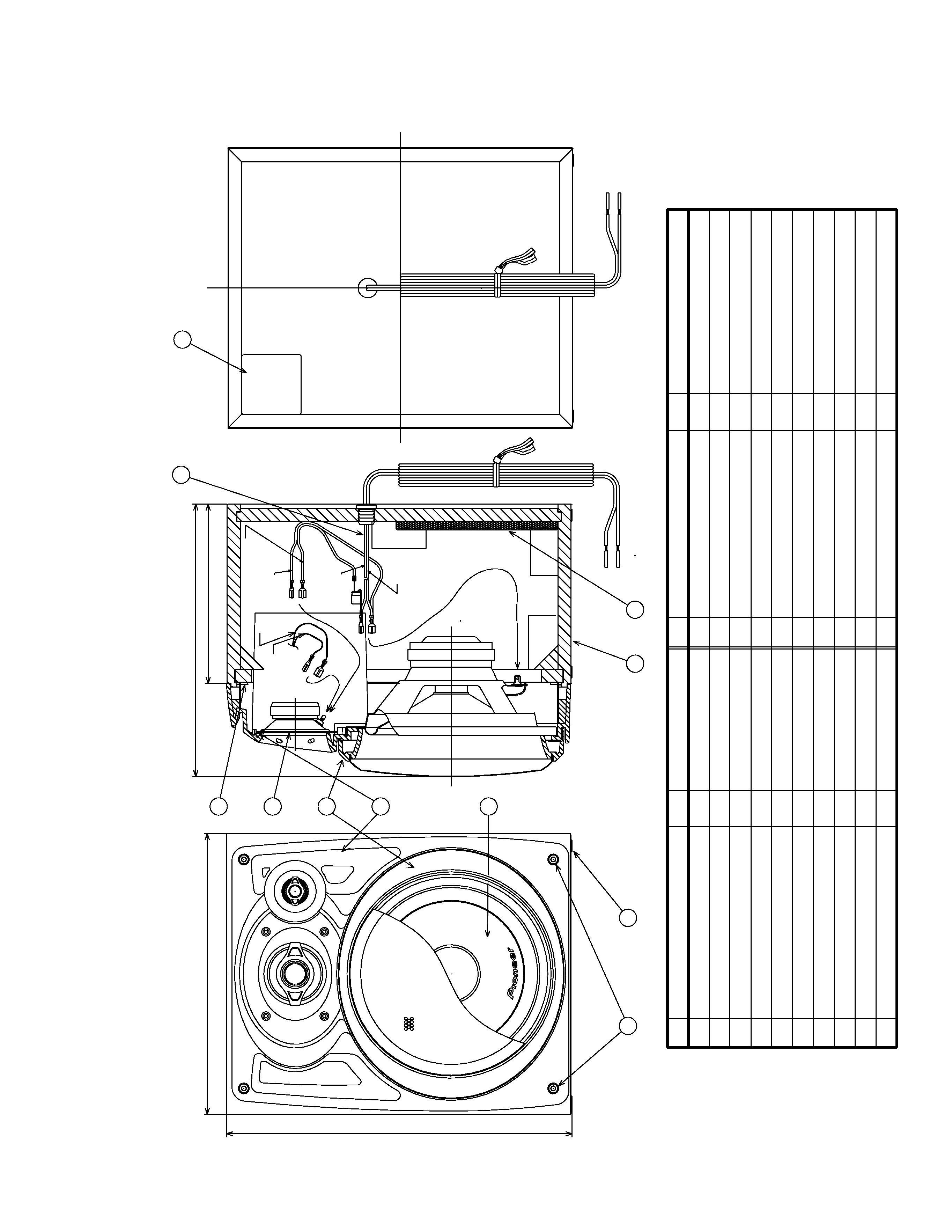
The cosmetic baffle assy is attached to the cabinet by 4 external
hexagon socket screws. To detach the cosmetic baffle assy,
loosen these screws by the hexagon screw driver. Then care-
fully disconnect the wires of the woofer and mid-range
mounted on the cosmetic baffle assy. To attach the cosmetic
baffle assy, replace it on the cabinet correctly and secure with 4
screws.
The woofer is attached to the cosmetic baffle assy together with
the cosmetic ring assy by 4 internal screws. To detach the
woofer (cosmetic ring assy), loosen these screws. To attach the
cosmetic ring assy, fit the notch of the cosmetic ring to the pro-
jection of the cosmetic baffle assy. To attach the woofer, face
its terminal downward, and fit the hole of the frame to the boss
of the cosmetic baffle assy. To attach the cosmetic ring assy
and woofer, replace it on the cosmetic baffle assy correctly and
secure with 4 screws.
The mid-range is attached to the cosmetic baffle assy by 2 in-
ternal screws. To detach the mid-range, loosen these screws.
Then carefully disconnect the wires of the tweeter mounted on
the cosmetic baffle assy by adhesion. To attach the mid-range,
replace it on the cosmetic baffle assy correctly and secure with
2 screws.
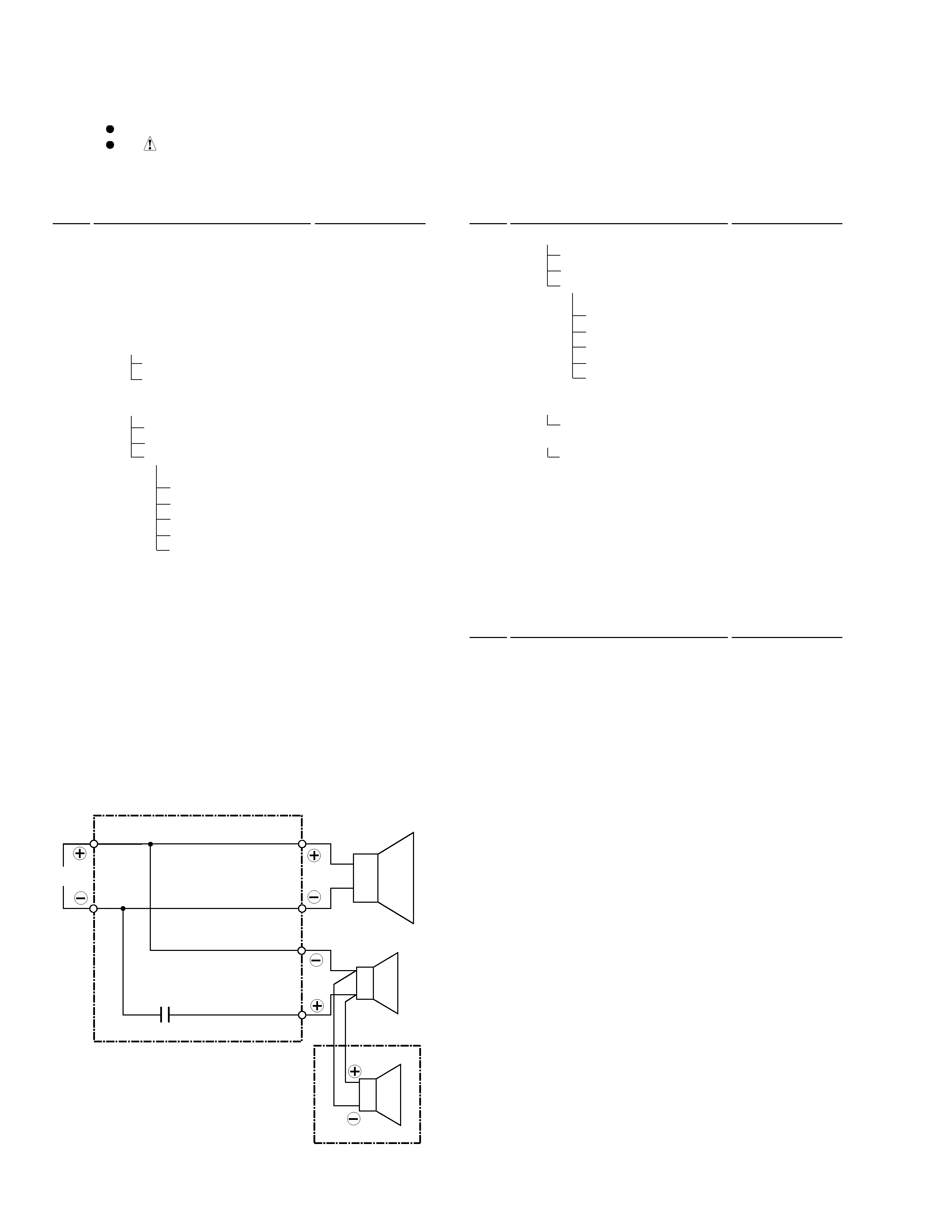
The network assy is attached to the back board of the cabinet
by press-fitting. To detach the network assy, strike the cord-
stopper of the network assy with a hammer from inside of the
cabinet. To attach the network assy, replace it on the back
board of the cabinet correctly by press-fitting.
When exchange the tweeter, do it with the cosmetic baffle
assy.