ORDER NO.
PIONEER CORPORATION 4-1, Meguro 1-chome, Meguro-ku, Tokyo 153-8654, Japan
PIONEER ELECTRONICS (USA) INC. P.O. Box 1760, Long Beach, CA 90801-1760, U.S.A.
PIONEER EUROPE NV Haven 1087, Keetberglaan 1, 9120 Melsele, Belgium
PIONEER ELECTRONICS ASIACENTRE PTE. LTD. 253 Alexandra Road, #04-01, Singapore 159936
PIONEER CORPORATION 2006
RRV3338
CONTENTS
1. PARTS LIST ................................................................................. 2
2. FOR PRECAUTION OF REASSEMBLY AND DISASSEMBLY ... 5
3. SCHEMATIC DIAGRAM ............................................................... 9
4. JIG .............................................................................................. 10
T ZZS FEB. 2006 Printed in Japan
NOTE
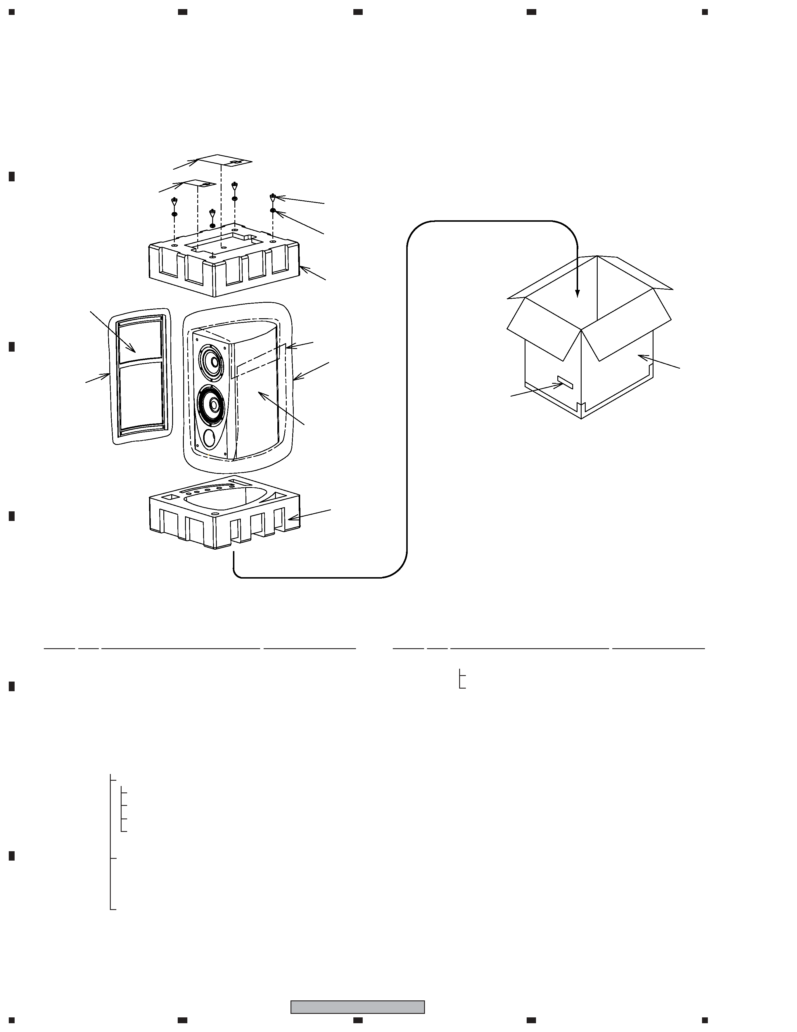
For better audio quality, the receptacle terminals and terminal fittings of the speaker unit are
soldered. When disassembling/reassembling the speaker unit, be sure to follow the instructions
in this manual. If you will be working on the speaker unit with it turned on its side, lay it on a
piece of soft cloth, etc., to protect the cabinet from being scratched.
SPEAKER SYSTEM
S-2EX
XTW/E
This service manual is intended for qualified service technicians; it is not meant for the casual do-it-
yourselfer. Qualified technicians have the necessary test equipment and tools, and have been trained to
properly and safely repair complex products such as those covered by this manual.
Improperly performed repairs can adversely affect the safety and reliability of the product and may void the
warranty. If you are not qualified to perform the repair of this product properly and safely, you should not risk
trying to do so and refer the repair to a qualified service technician.
WARNING
This product contains lead in solder and certain electrical parts contain chemicals which are known to the state of California to
cause cancer, birth defects or other reproductive harm.
Health & Safety Code Section 25249.6 Proposition 65