RM-V2550U
3
Leakage Current Cold Check
With the AC plug removed from l20V AC 60Hz source, place
a jumper across the two plug prongs. Turn the AC power
switch on. Using an insulation tester (DC 500V), connect
one lead to the jumpered AC plug and touch the other lead to
each exposed metal part ( input/ output terminals,
screwheads, metal overlays, control shafts, etc.), particu-
larly any exposed metal part having a return path to the
chassis. Exposed metal parts having a return path to the
chassis should have a minimum resistor reading of 0.3MW
and a maximum resistor reading of 5MW. Any resistor value
below or above this range indicates an abnormality which
requires corrective action. Exposed metal parts not having a
return path to the chassis will indicate an open circuit.
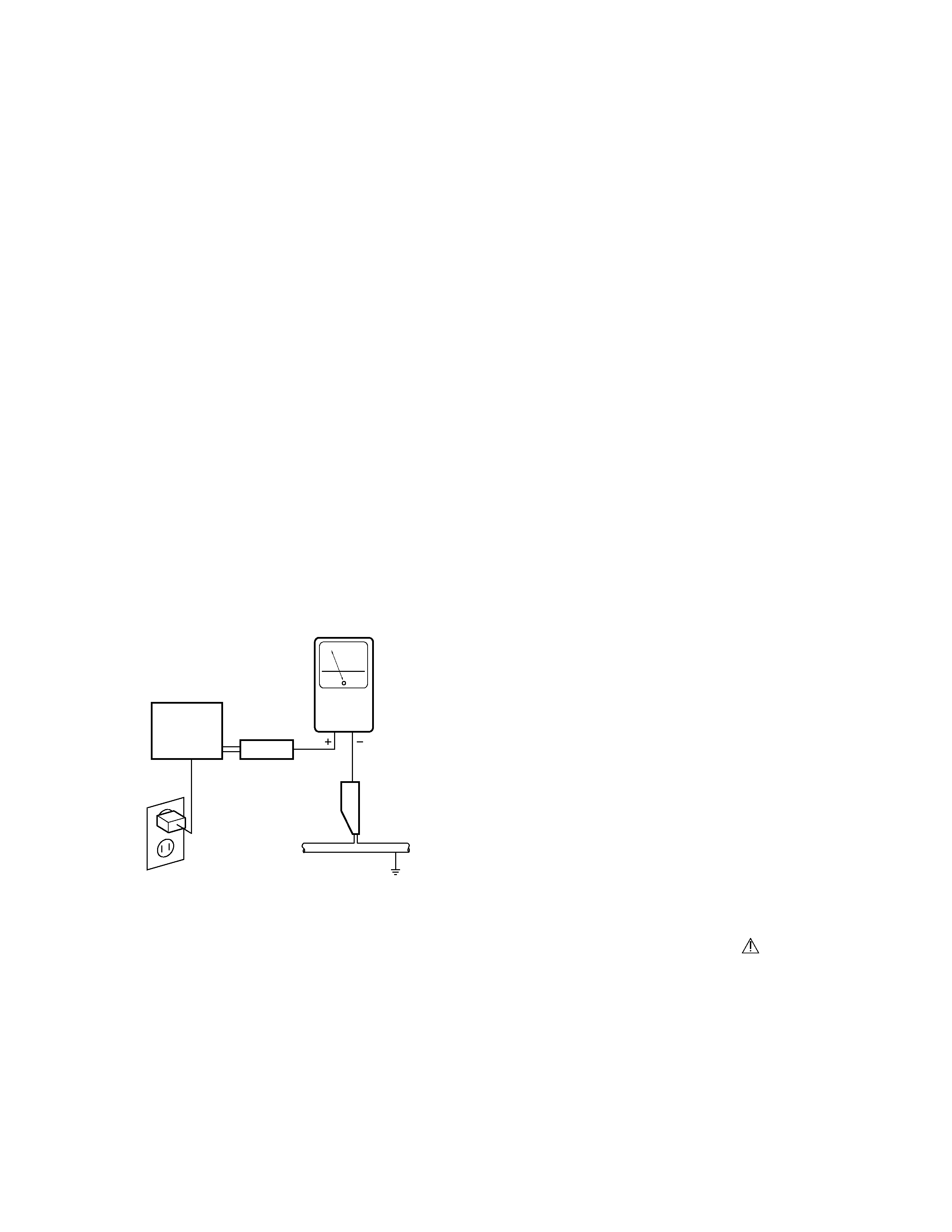
Leakage Current Hot Check
Plug the AC line cord directly into a 120V AC 60Hz out-
let ( do not use an isolation transformer for this check
). Turn the AC power switch on.
Using a "Leakage Current Tester ( Simpson Model 229
equivalent )", measure for current from all exposed
metal parts of the cabinet ( input / output terminals,
screwheads, metal overlays, control shaft, etc. ), par-
ticularly any exposed metal part having a return path
to the chassis, to a known earth ground ( water pipe,
conduit, etc.). Any current measured must not exceed
0.5mA.
Device
under
test
Leakage
current
tester
Reading should
not be above
0.5 mA
Also test with
plug reversed
(Using AC adapter
plug as required)
Test all
exposed metal
surfaces
Serviceman Warning
In the status of the black picture ( video muting is
being applied ) when no signal is input, high volt-
age of this set during operation is less than 30.9kV.
In case any component having some relation to the
high voltage is replaced, confirm that the high volt-
age is lower than 30.9kV in the status of the black
picture when no signal is input.
To measure H.V. use a high impedance H.V. meter.
Connect ( - ) to earth and ( + )to the FBT anode cable
connector.
(Refer to page 90)
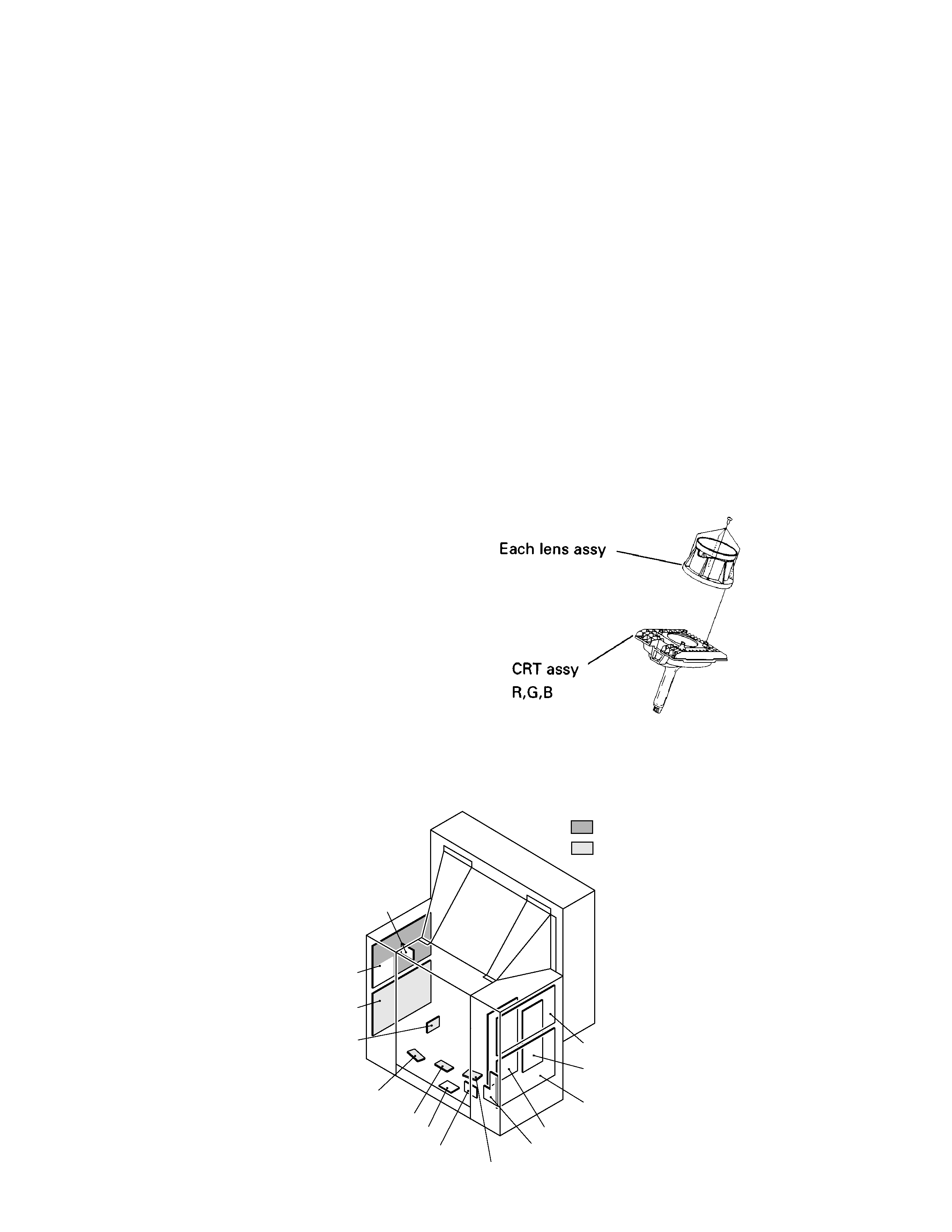
X-radiation
TUBE: The primary source of X-radiation in this set
is the picture tube.
For continued X-radiation protection, the replace-
ment tube must be the same type as the original,
PIONEER approved type.
The picture tube (the CRT assy R, G, B ) use in this
set holds complete guarantee against X-ray radia-
tion when the X-ray is sealed ( See page 4 ). Ac-
cordingly, when the current in flowing to the pic-
ture tube be sure to perform it by putting the tube
into X-ray sealed applied state. Avoid absolutely to
flow the current to the picture tube itself. More-
over, when the voltage of the high voltage circuit
becomes abnormally a little higher, the picture
tube radiates X-rays. Accordingly, when servicing
the high voltage circuit be sure to replace as an as-
sembly with the POWER SUPPLY assy in the
manner in which has been adjusted to perform nor-
mal operation.
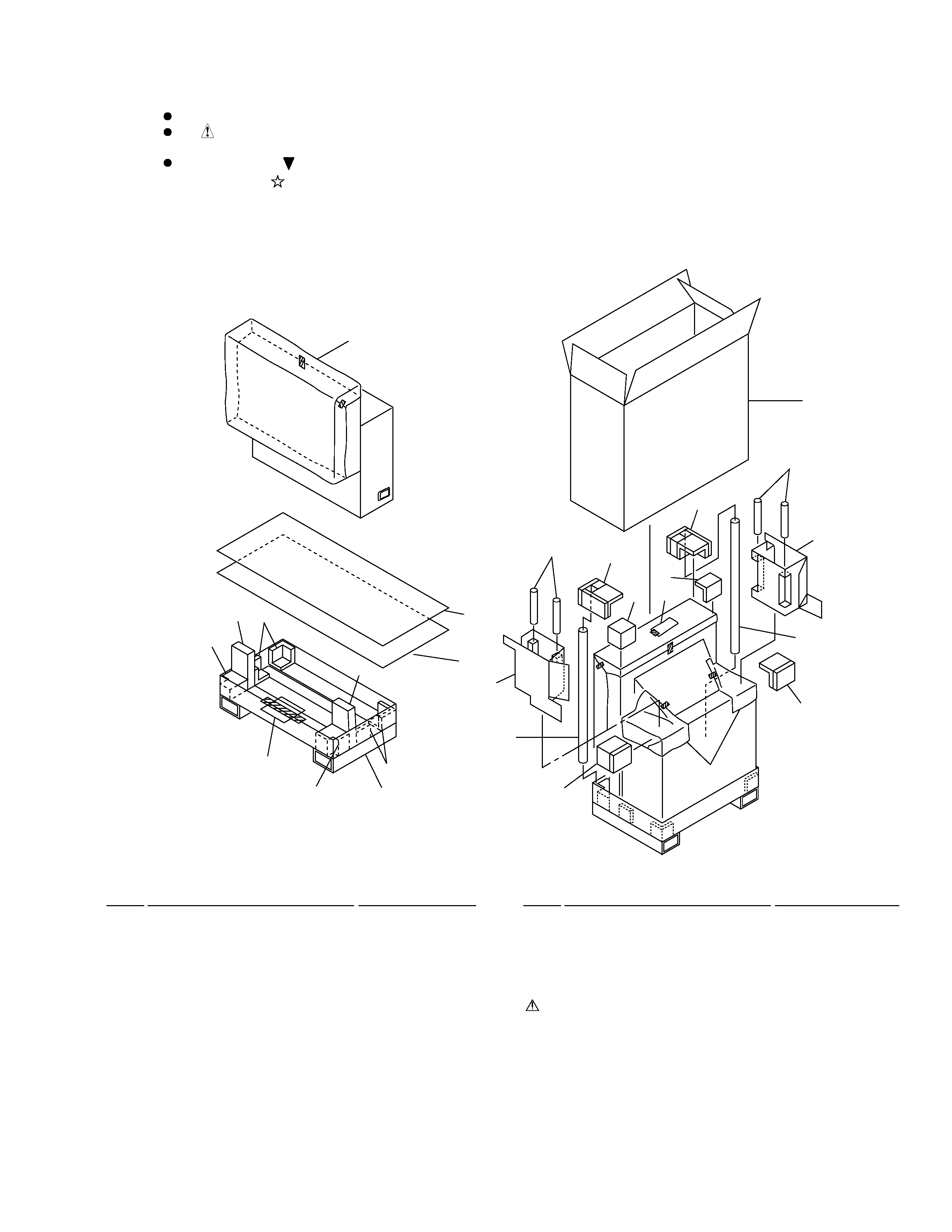
1.2 PRODUCT SAFETY NOTICE
Many electrical and mechanical parts in PIONEER
set have special safety related characteristics.
These are often not evident from visual inspection
nor the protection afforded by them necessarily
can be obtained by using replacement components
rated for higher voltage, wattage, etc. Replacement
parts which have these special safety characteris-
tics are identified in this Service Manual.
Electrical components having such features are
identified by marking with a
on the schematics
and on the parts list in this Service Manual.
The use of a substitute replacement component
which does not have the same safety characteris-
tics as the PIONEER recommended replacement
one, shown in the parts list in this Service Manual,
may create shock, fire, X-radiation, or other
hazards.
Product Safety is continuously under review and
new instructions are issued from time to time. For
the latest information, always consult the current
PIONEER Service Manual. A subscription to, or ad-
ditional copies of PIONEER Service Manual may be
obtained at a nominal charge from PIONEER.
ANY MEASUREMENTS NOT WITHIN THE LIMITS OUTLINED
ABOVE ARE INDICATIVE OF A POTENTIAL SHOCK HAZARD
AND MUST BE CORRECTED BEFORE RETURNING THE SET TO
THE CUSTOMER.
High Voltage
This set is provided with a X-ray protection for clearly
indicating that voltage has increased in excess of a
predetermined value. Comply with all notes described
in this Service Manual regarding this hold down cir-
cuit when servicing, so that this X-ray protection may
correctly by operated.