PIONEER PRS-D1100M/XU/UC Owner's Manual

Cover page of PIONEER PRS-D1100M/XU/UC Owner's Manual

Owner's Manual for PIONEER PRS-D1100M/XU/UC, downloadable as a PDF file.

We also have service manual to this model.

Manual details

  • Immediate download after payment.
  • Delivered as a PDF file.
  • The manual has 49 pages
  • File size: 1.72 MB
  • Available language versions: French, English, Spanish
  • Different language versions may vary sligthly in file size and page count.

We guarantee that...

  • our manuals are complete,
  • our manuals are checked with antivirus,
  • We'll issue refund if the manual is damaged, incomplete or unreadable (our refund policy)

Sample pages

Thumbnail of page 1Thumbnail of page 2Thumbnail of page 3Thumbnail of page 4
Thumbnail of page 5Thumbnail of page 6Thumbnail of page 7Thumbnail of page 8
Thumbnail of page 9
background image
ENGLISH
FRANÇAIS
ESPAÑOL
ITALIANO
NEDERLANDS
êìëëäàâ
CLASS D MONO AMPLIFIER
AMPLIFICATEUR MONO DE CLASSE D
Owner's Manual
PRS-D1100M
Mode d'emploi
background image
ENGLISH
FRANÇAIS
ESPAÑOL
ITALIANO
NEDERLANDS
êìëëäàâ
CLASS D MONO AMPLIFIER
AMPLIFICATEUR MONO DE CLASSE D
Owner's Manual
PRS-D1100M
Mode d'emploi
background image
1
Before Using This Product ...................... 1
Information to User .......................................... 1
Important .......................................................... 1
Visit our website ................................................ 2
About This Product ............................................ 2
CAUTION ........................................................ 2
WARNING ........................................................2
Setting the Unit .......................................... 3
Terminal Cover ................................................ 3
Power Indicator ................................................ 3
Subsonic Select Switch .................................... 3
Bass Boost Control ............................................ 3
BFC (Beat Frequency Control) Switch ............ 3
MODE SELECT Switch .................................. 4
Gain Control ...................................................... 4
Cut Off Frequency Control for LPF .................. 4
Input Switch ...................................................... 4
POWER MODE Switch .................................... 4
Connecting the Unit .................................. 5
Connection Diagram ........................................ 6
Connecting the Power Terminal ........................ 7
Connecting the Speaker Output Terminals ...... 8
Using the Speaker Input .................................... 8
Connecting the Speaker Wires .......................... 9
Installation ................................................ 13
Example of installation on the floor mat
or on the chassis ...................................... 14
Replacing the terminal cover .......................... 14
Specifications .......................................... 15
Thank you for purchasing this PIONEER
product. It is designed to give you many
years of enjoyment.
PIONEER SUGGESTS USING A PRO-
FESSIONAL INSTALLER DUE TO THE
COMPLEXITY OF THIS PRODUCT.
Please read all instructions and WARN-
INGS in this manual before attempting
operation. Should you have any questions,
contact your nearest Pioneer authorized
dealer or installation specialist.
Information to User
Alteration or modifications carried out
without appropriate authorization may
invalidate the user's right to operate the
equipment.
Important
The serial number of this amplifier is writ-
ten on the bottom of the unit. For your
own security and convenience, write it
down on the enclosed warranty card. Keep
the card handy for future reference.
Contents
Before Using This Product
After-sales service for Pioneer
products
Please contact the dealer or distributor from where
you purchased the product for its after-sales ser-
vice (including warranty conditions) or any other
information. In case the necessary information is
not available, please contact the companies listed
below:
Please do not ship your product to the companies
at the addresses listed below for repair without
advance contact.
7 U.S.A.
Pioneer Electronics (USA) Inc.
CUSTOMER SUPPORT DIVISION
P.O. Box 1760
Long Beach, CA 90801-1760
800-421-1404
7 CANADA
Pioneer Electronics of Canada, Inc.
CUSTOMER SATISFACTION
DEPARTMENT
300 Allstate Parkway
Markham, Ontario L3R OP2
1-877-283-5901
For warranty information please see the Limited
Warranty sheet included with your product.
background image
ENGLISH
ESPAÑOL
DEUTSCH
FRANÇAIS
ITALIANO
NEDERLANDS
êìëëäàâ
2
Visit our website
Visit us at the following site:
1 Register your product. We will keep the details of
your purchase on file to help you refer to this
information in the event of an insurance claim
such as loss or theft.
2 Receive updates on the latest products and tech-
nologies.
3 Download owner's manuals, order product cata-
logues, research new products, and much more.
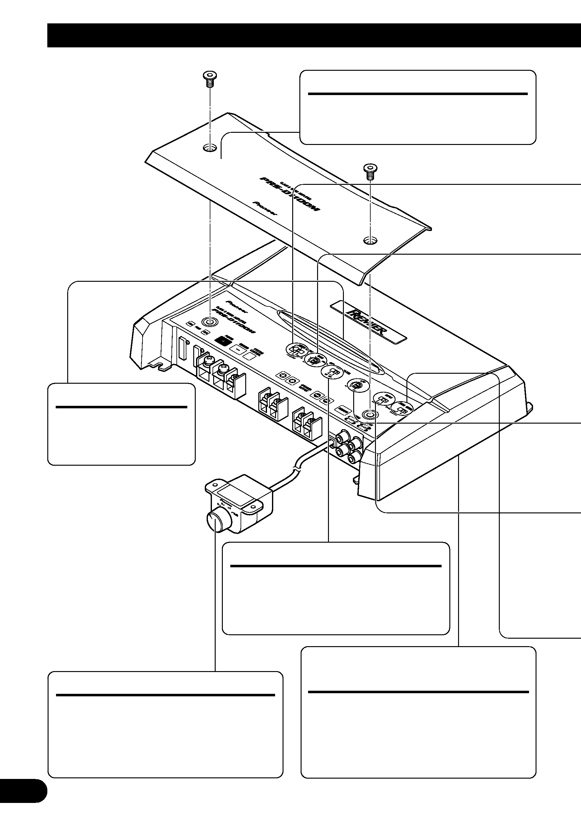
About This Product
This product is a class D amplifier for the
subwoofer. If both L (left) and R (right)
channels are connected to the RCA input
of this product, output is mixed because
this product is a mono amplifier.
CAUTION
Never replace the fuse with one of greater
value or rating than the original fuse. Use of
an improper fuse could result in overheating
and smoke and could cause damage to the
product and injury including burns.
WARNING
· Handling the cord on this product or cords associat-
ed with accessories sold with the product will
expose you to lead, a chemical known to the State
of California and other governmental entities to
cause cancer and birth defects or other reproductive
harm. Wash hands after handling.
· Always use the special red battery and ground
wire [RD-223] and [RD-222], which are sold sep-
arately. Connect the battery wire directly to the
car battery positive terminal (+) and the ground
wire to the car body. There is the risk of a fuse
burning out if only one of these is connected.
· Do not touch the amplifier with wet hands.
Otherwise you may get an electric shock. Also, do
not touch the amplifier when it is wet.
· For traffic safety and to maintain safe driving
conditions, keep the volume low enough so that
you can still hear normal traffic sound.
· Check the connections of the power supply and
speakers if the fuse of the separately sold battery
wire or the amplifier fuse blows. Detect the cause
and solve the problem, then replace the fuse with
another one of the same size and rating.
· To prevent malfunction of the amplifier and speak-
ers, the protective circuit will cut the power supply
to the amplifier (sound will stop) when an abnor-
mal condition occurs. In such a case, switch the
power to the system OFF and check the
connection of the power supply and speakers.
Detect the cause and solve the problem.
· Contact the dealer if you cannot detect the cause.
· To prevent an electric shock or short-circuit
during connection and installation, be sure to
disconnect the negative (­) terminal of the battery
beforehand.
· Confirm that no parts are behind the panel when
drilling a hole for installation of the amplifier. Be
sure to protect all cables and important equipment
such as fuel lines, brake lines and the electrical
wiring from damage.
· DO NOT allow amplifier to come into contact with
liquids due to, for example, the location where the
amplifier is installed. Electrical shock could result.
Also, amplifier and speaker damage, smoke, and
overheating could result from contact with liquids.
In addition, the amplifier surface and the surface of
any attached speakers could become hot to the
touch and minor burns could result.
background image
3
Setting the Unit
Power Indicator
The power indicator
lights when the power
is switched on.
Terminal Cover
Before setting up the unit, unfasten the
screws with a 4 mm hexagonal wrench
and remove the terminal cover.
Bass Boost Control
You can select a bass boost level from
0, 6, 9 and 12 dB.
For instruction of connecting the bass
boost remote control to the amplifier,
see the "Connection Diagram" section.
BFC (Beat Frequency Control)
Switch
BFC switch is on the bottom of the unit.
If you hear a beat while listening to an
AM broadcast with your car stereo,
change the BFC switch using a small
standard tip screwdriver.
Subsonic Select Switch
The subsonic filter cuts inaudible
frequencies below 20 Hz to eliminate
unwanted vibrations and minimize
power loss.
· To adjust the switch, use standard tip screwdriver if needed.
background image
ENGLISH
ESPAÑOL
DEUTSCH
FRANÇAIS
ITALIANO
NEDERLANDS
êìëëäàâ
4
Gain Control
If the sound level is too low, even when the volume of the car stereo used along with this
power amplifier is turned up, turn gain control clockwise. If the sound distorts when the vol-
ume is turned up, turn the gain control counter-clockwise.
· When using with an RCA equipped car stereo (standard output of 500 mV), set to the NORMAL
position. When using with an RCA equipped Pioneer car stereo with max. output of 4 V or more,
adjust level to match the car stereo output level.
· If you hear too much noise when using the speaker input terminals, turn the gain control
counter-clockwise.
Input Switch
It is possible to input from a car stereo external output or a car stereo speaker output. Switch
the input switch before turning on the power. Since switching the input switch while the
power is on can cause a loud noise to be emitted from the speakers, the power is turned off
by a protection function. When using an external output, slide the switch to the left. For
connection instructions, see the "Connection Diagram" section. When using a speaker out-
put, slide the switch to the right. In this case, it is necessary to use the supplied speaker input
wire with RCA pin cord. For details, see the "Using the Speaker Input" section.
MODE SELECT Switch
You can select amplifier's sync mode from MASTER, SYNC and SYNC INV. Set the
MODE SELECT switch to the MASTER position when using one amplifier only. When
using synchronously connecting two or more of these amplifiers in combination, set the first
amplifier to MASTER, and set the remaining amplifiers to SYNC or SYNC INV according
to the manner in which they are connected. The only time the amplifier is switched to the
SYNC INV mode is when amplifiers are synchronously connected with the ex. bridge.
When switching to the SYNC INV mode, the seal over the MODE SELECT switch must be
peeled off and you can find SYNC INV switch. Peel off the seal after checking that connec-
tions are correct. See the "Connecting the Speaker Wires" section for details on the MODE
SELECT switch.
POWER MODE Switch
When using speakers with synthetic impeadance 2
to 8 , slide the switch to the right
(NORMAL). When using speakers with synthetic impeadance from 1
to less than 2 ,
slide the switch to the left (HI-CURRENT). These settings are only used when using a sin-
gle amplifier. See the "Connecting the Speaker Wires" section when combining the use of
multiple amplifiers.
If the speaker impedance exceeds 2
(4 when using ex. bridge), although the POWER
MODE switch be may set to the HI-CURRENT position, setting to the NORMAL position
makes it possible to enjoy high power sound.
Cut Off Frequency Control for LPF
You can select a cut off frequency from 40 Hz to 240 Hz.

Reviews

There are no reviews of this manual yet.