ENGLISH
ESPAÑOL
DEUTSCH
FRANÇAIS
ITALIANO
NEDERLANDS
êìëëäàâ
Visit our website
Visit us at the following site:
1 Register your product. We will keep the details of
your purchase on file to help you refer to this
information in the event of an insurance claim
such as loss or theft.
2 Receive updates on the latest products and tech-
nologies.
3 Download owner's manuals, order product cata-
logues, research new products, and much more.
CAUTION
· Never replace the fuse with one of greater value
or rating than the original fuse. Use of an
improper fuse could result in overheating and
smoke and could cause damage to the product and
injury including burns.
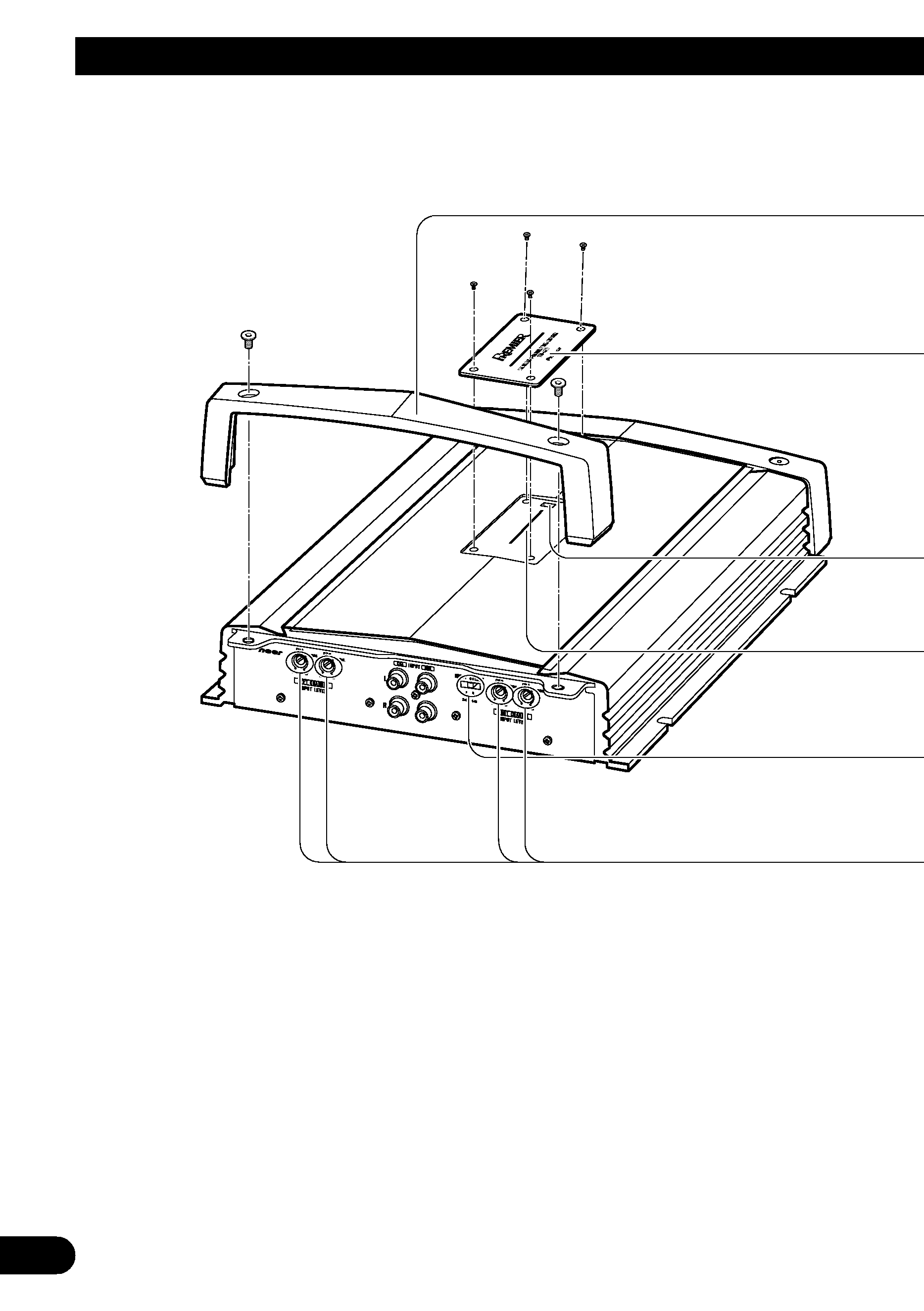
· Use the supplied hexagonal wrench to tighten
screws when fastening wires to the terminal or
when changing the direction of the badge. The use
of a long, commercially available hexagonal
wrench can cause excessive torque to be applied
possibly resulting in damage to terminals and
wires.
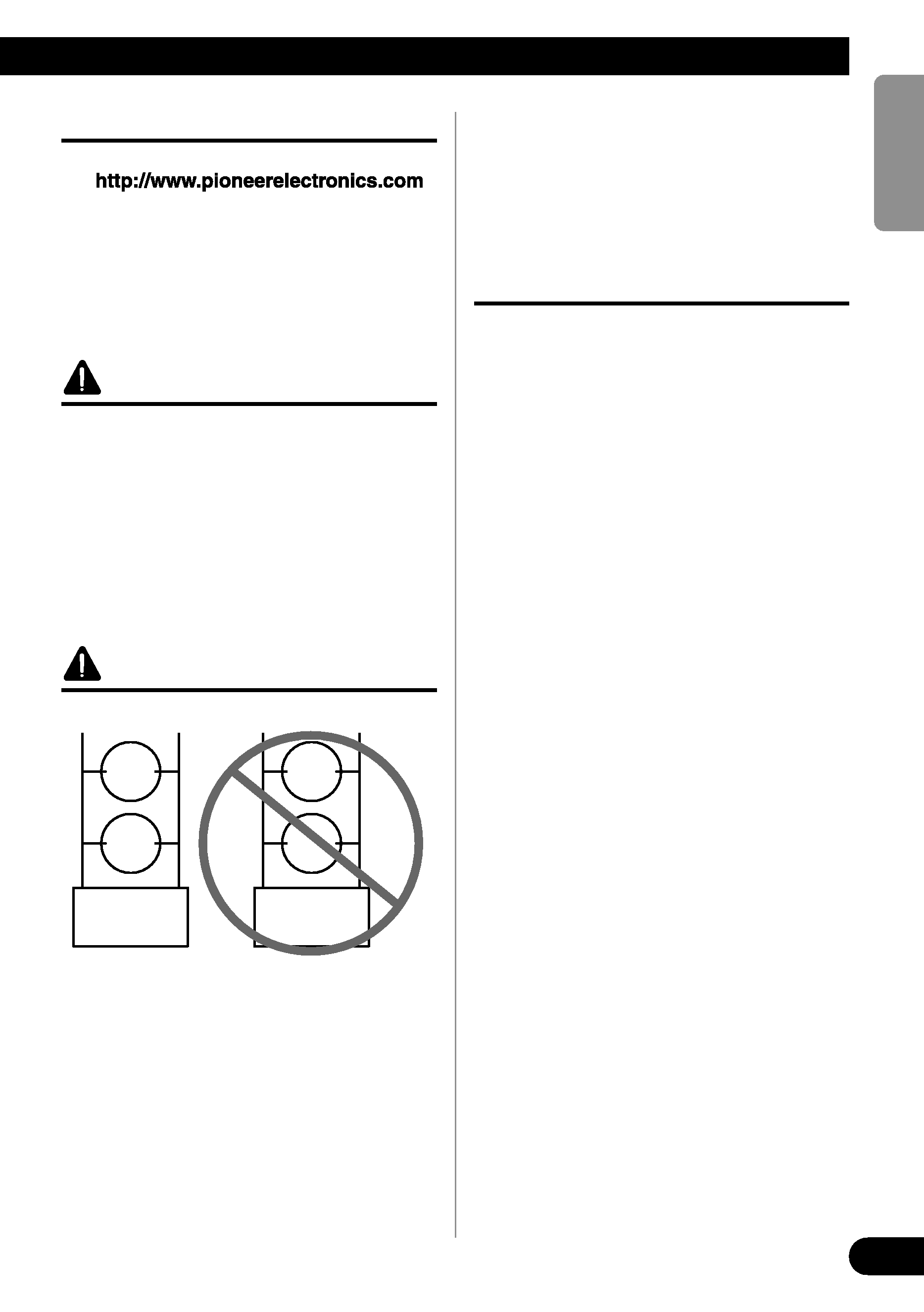
CAUTION
DO NOT install or use your Pioneer amplifier
by wiring speakers rated at 4
(or lower) in
parallel to achieve a 2
(or lower) bridged
mode (Diagram B).
Amplifier damage, smoke, and overheating
could result from improper bridging. The ampli-
fier surface could also become hot to the touch
and minor burns could result.
To properly install or use a bridged mode for a
two-channel amplifier and achieve a 4
load,
wire two 8
speakers in parallel with Left +
and Right - (Diagram A) or use a single 4
speaker. For a four-channel amplifier, follow
the speaker output connection diagram for
bridging as shown on the back of your amplifi-
er, and wire two 8
speakers in parallel to
achieve a 4
load or use a single 4 speaker
per channel.
If you have any questions or concerns, please
contact your local authorized Pioneer dealer or
call Pioneer customer service.
WARNING
· Handling the cord on this product or cords associ-
ated with accessories sold with the product may
expose you to chemicals listed on proposition 65
known to the State of California and other gov-
ernmental entities to cause cancer and birth
defects or other reproductive harm. Wash hands
after handling.
· We recommended that you use the special red
battery and ground wire [RD-228], which is sold
separately. Connect the battery wire directly to
the car battery positive terminal (+) and the
ground wire to the car body.
· Do not touch the amplifier with wet hands.
Otherwise you may get an electric shock. Also, do
not touch the amplifier when it is wet.
· For traffic safety and to maintain safe driving
conditions, keep the volume low enough so that
you can still hear normal traffic sound.
· Check the connections of the power supply and
speakers if the fuse of the separately sold battery
wire or the amplifier fuse blows. Detect the cause
and solve the problem, then replace the fuse with
another one of the same size and rating.
· To prevent malfunction of the amplifier and
speakers, the protective circuit will cut the power
supply to the amplifier (sound will stop) when an
abnormal condition occurs. In such a case, switch
the power to the system OFF and check the
connection of the power supply and speakers.
Detect the cause and solve the problem.
· Contact the dealer if you cannot detect the cause.
· To prevent an electric shock or short-circuit
during connection and installation, be sure to
disconnect the negative () terminal of the battery
beforehand.
· Confirm that no parts are behind the panel when
drilling a hole for installation of the amplifier. Be
sure to protect all cables and important equipment
such as fuel lines, brake lines and the electrical
wiring from damage.
· DO NOT allow amplifier to come into contact
with liquids due to, for example, the location
where the amplifier is installed. Electrical shock
could result. Also, amplifier and speaker damage,
smoke, and overheating could result from contact
with liquids. In addition, the amplifier surface and
the surface of any attached speakers could
become hot to the touch and minor burns could
result.
Diagram A - Proper
8
Speaker
+-
8
Speaker
Pioneer
Amplifier
4
Bridged Mode
+
L+
R-
-
Diagram B - Improper
4
Speaker
+-
4
Speaker
Pioneer
Amplifier
2
Bridged Mode
+
L+
R-
-
2