5
English
English
CABINET MAINTENANCE
÷ Use a polishing cloth or dry cloth to wipe off dust and
dirt.
÷ When the cabinet is very dirty, wipe with a soft cloth
moistened with water-diluted cleanser; then wipe again
with a dry cloth. Do not use furniture wax or cleaners.
They may damage the surface of the cabinet.
÷ Never use thinner, benzine, insecticide sprays and
other chemicals on or near the cabinets, since these
will corrode the surfaces.
÷ When a chemical cloth is used, read the cautions for
the chemical cloth carefully.
SPECIFICATIONS
Cabinet: Bass-reflex type
Used speakers (two-way system):
Woofer (for low tones) ........................... 7 cm cone type
Tweeter (for high tones) ........................ 5 cm cone type
Nominal impedance ..................................................... 8
Frequency Range ..................................... 65 Hz to 35 kHz
Sensitivity (1 w, 1 m) ................................................ 85 dB
Permissible input :
Max. input .............................................................. 13 W
Rated input ............................................................... 4 W
Crossover frequency ................................................ 4 kHz
External Dimensions
.......................... 90 mm (W)
× 880 mm (H) × 92 mm (D)
Weight ..................................................................... 2.4 kg
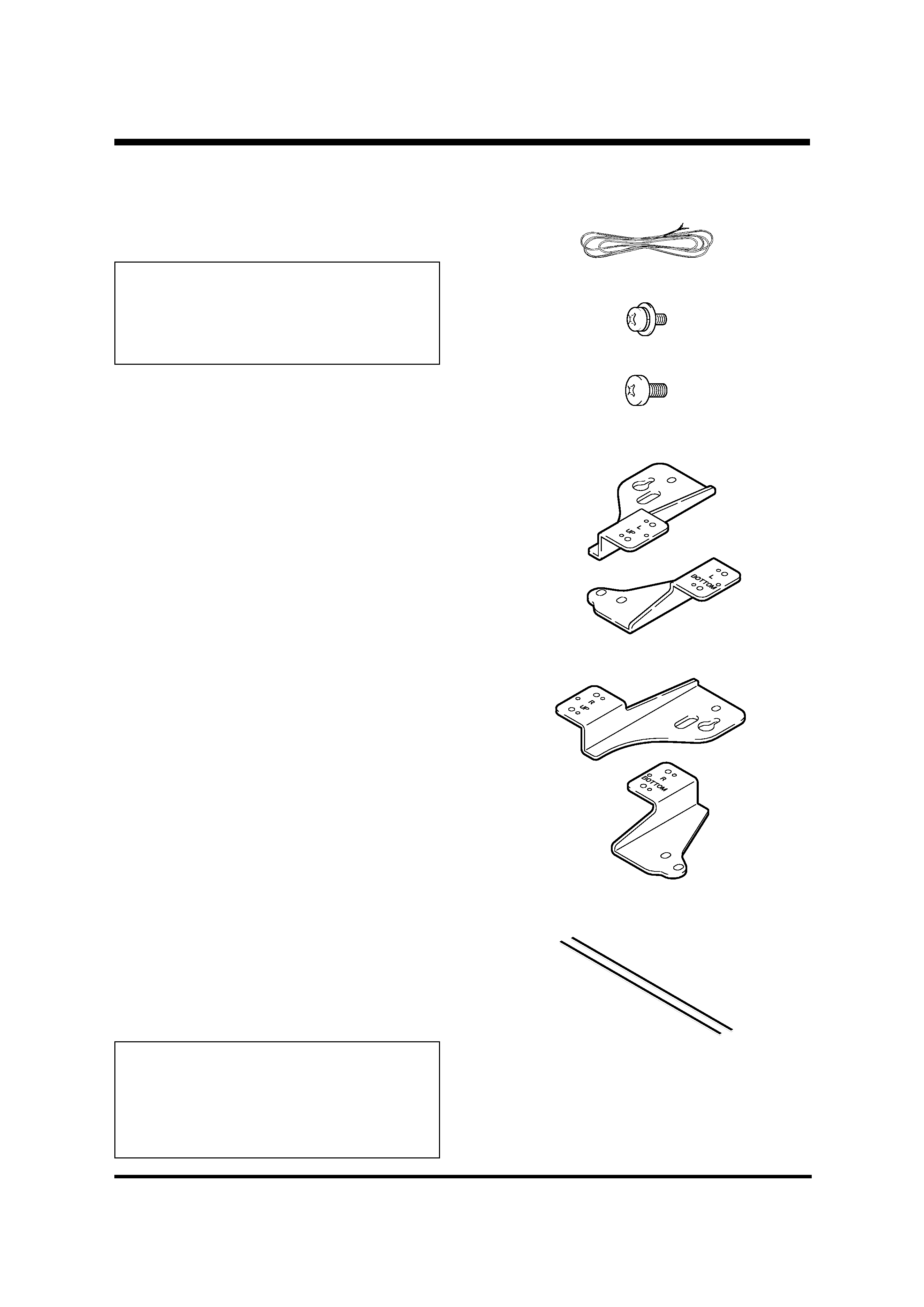
Accessory parts (for 2 speakers)
............................................................ Speaker cable
× 2
................................................ Screw (M4
× 10 mm) × 8
................................................ Screw (M5
× 10 mm) × 8
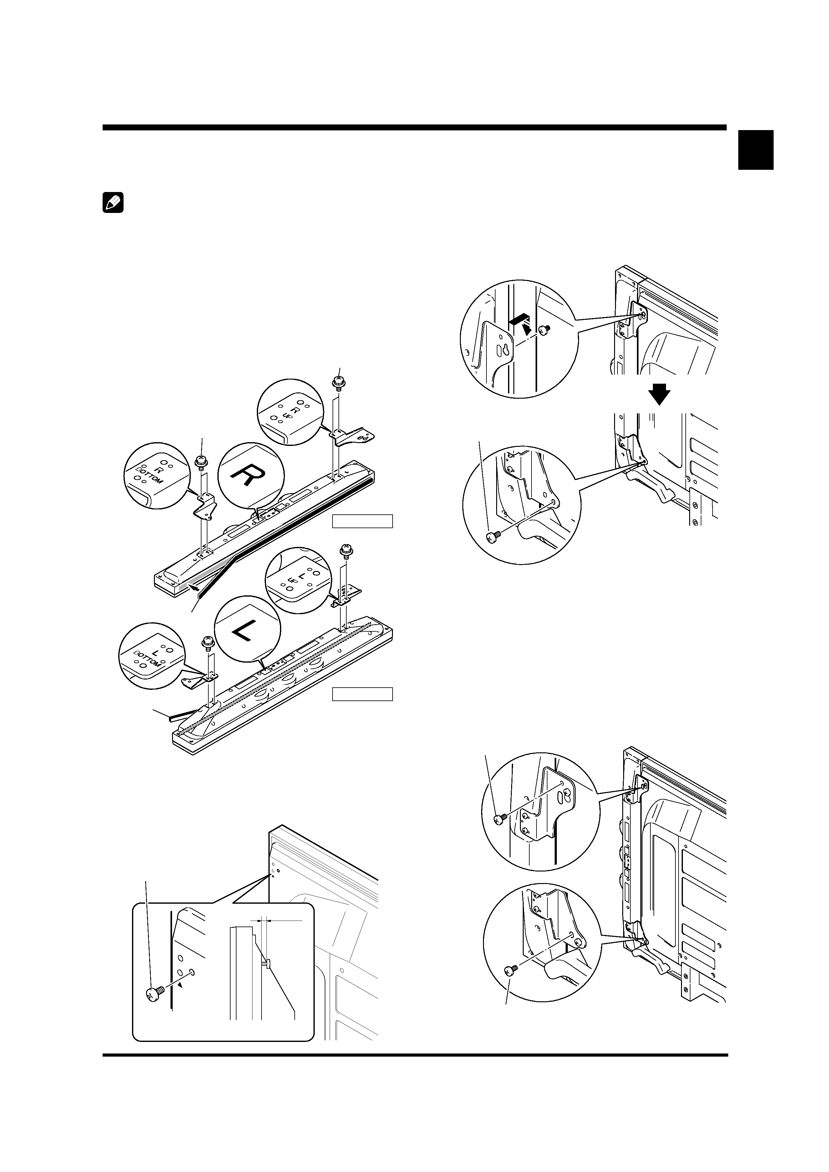
............................................................................. Bracket
LEFT-TOP
× 1
LEFT-BOTTOM
× 1
RIGHT-TOP
× 1
RIGHT-BOTTOM
× 1
.................................................................... Cushions
× 2
.............................................. Operating Instructions
× 1
NOTE:
Specifications and design subject to possible modification
without notice, due to improvements.
Published by Pioneer Corporation.
Copyright © 2006 Pioneer Corporation.
All rights reserved.
IMPORTANT NOTICE RECORD THE MODEL NUMBER AND SERIAL NUMBERS OF THIS EQUIPMENT BELOW.
THE NUMBERS ARE ON THE REAR.
MODEL NO.
SERIAL NO.
KEEP THESE NUMBERS FOR FUTURE USE.
D1-4-2-6-2_En
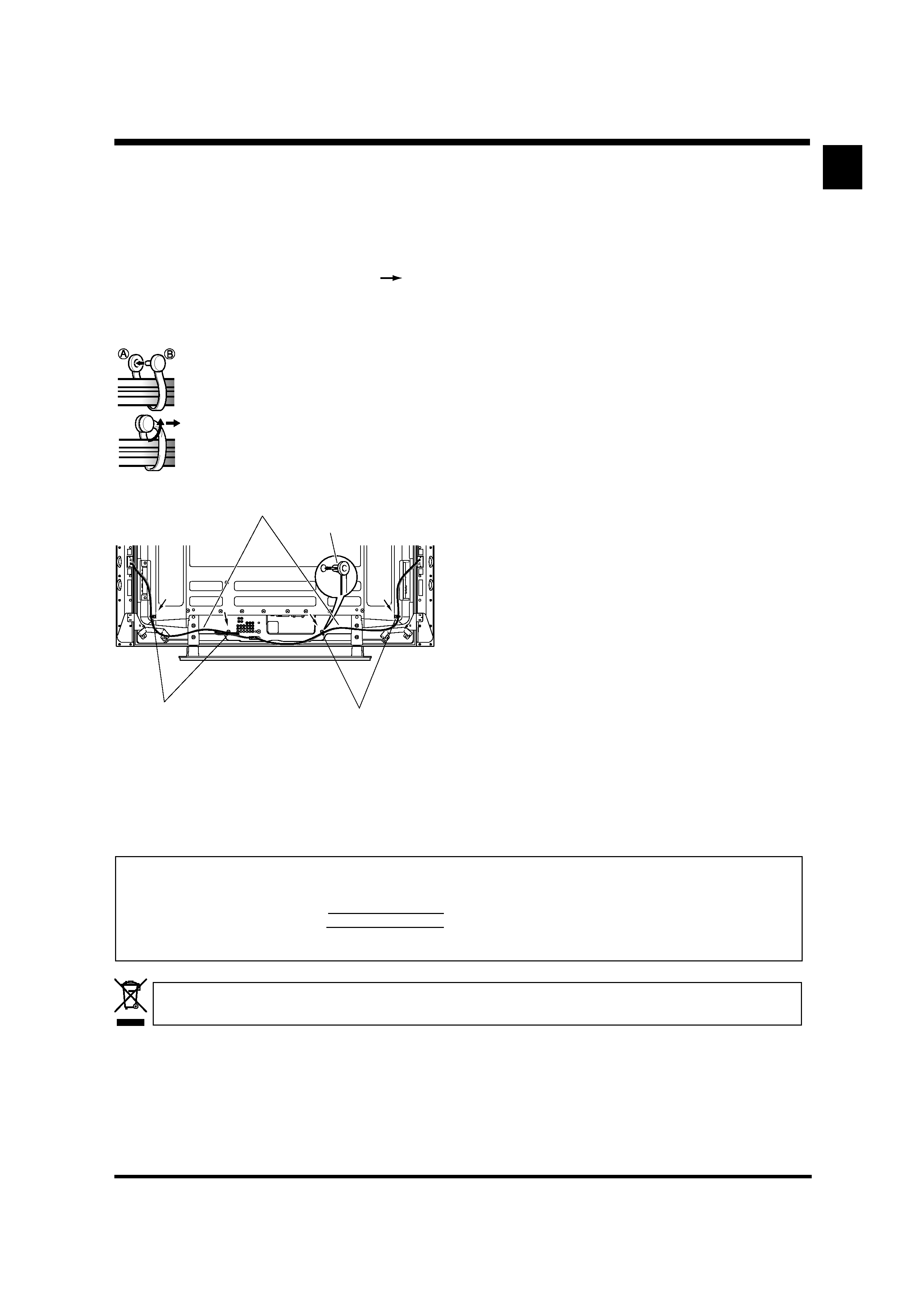
HOW TO ROURE CABLES
Speed clamps are included with the Plasma Display for
tidying your cables and keeping extra cable length out of
the way.
Attach speed clamps at the direction of the running cables.
*
When the Pioneer stand, sold separately, is not used, use the 4
holes that are marked with arrows in the diagram (
) as the
holes for attaching speed clamps.
Using Speed Clamps
Wrap the speed clamp around the bundled
cables and press B into hole A.
To remove a speed clamp, use pliers to
twist it 90° and then pull it out. (This may
result in weakening or damaging the
clamp.)
If you want to dispose this product, do not mix it with general household waste. There is a separate collection system for used
electronic products in accordance with legislation that requires proper treatment, recovery and recycling.
Private households in the 25 member states of the EU, in Switzerland and Norway may return their used electronic products free of charge to
designated collection facilities or to a retailer (if you purchase a similar new one).
For countries not mentioned above, please contact your local authorities for the correct method of disposal.
By doing so you will ensure that your disposed product undergoes the necessary treatment, recovery and recycling and thus prevent potential
negative effects on the environment and human health.
K058_En
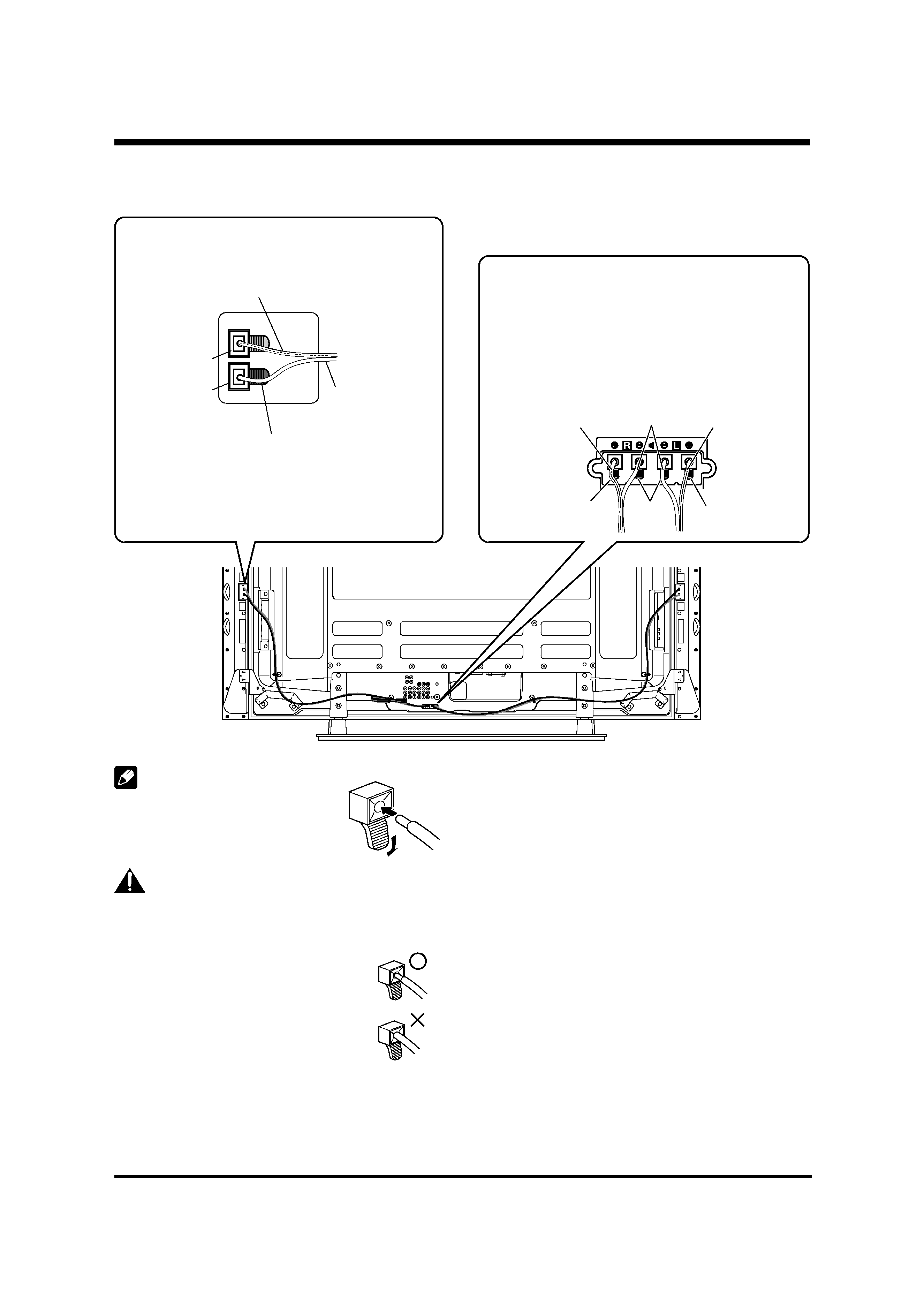
Rear of Display
Speaker Cable
Speed Clamp
Mounting Hole
Speed Clamp
Speed Clamp
Mounting Hole