PIONEER PDP-S41 Owner's Manual

Cover page of PIONEER PDP-S41 Owner's Manual

Owner's Manual for PIONEER PDP-S41, downloadable as a PDF file.

We also have service manual to this model.

Manual details

  • Immediate download after payment.
  • Delivered as a PDF file.
  • The manual has 39 pages
  • File size: 21.68 MB
  • Available language versions: French, English, Spanish, Dutch, German, Italian
  • Different language versions may vary sligthly in file size and page count.

We guarantee that...

  • our manuals are complete,
  • our manuals are checked with antivirus,
  • We'll issue refund if the manual is damaged, incomplete or unreadable (our refund policy)

Sample pages

Thumbnail of page 1Thumbnail of page 2Thumbnail of page 3Thumbnail of page 4
Thumbnail of page 5Thumbnail of page 6Thumbnail of page 7Thumbnail of page 8
Thumbnail of page 9
background image
PDP-S41
Operating Instructions
Mode d'emploi
Bedienungsanleitung
Istruzioni per l'uso
Gebruiksaanwijzing
Manual de instrucciones
Speaker System
Enceinte acoustique
Lautsprechersystem
Sistema di diffusori
Luidsprekersysteem
Sistema de altavoces
background image
PDP-S41
Operating Instructions
Mode d'emploi
Bedienungsanleitung
Istruzioni per l'uso
Gebruiksaanwijzing
Manual de instrucciones
Speaker System
Enceinte acoustique
Lautsprechersystem
Sistema di diffusori
Luidsprekersysteem
Sistema de altavoces
background image
English
2
Thank you for buying this Pioneer product.
Please read through these operating instructions before using
your speaker system so you will know how to make the
most of its performance. After you have finished reading the
instructions, put them away in a safe place for future
reference.
WARNING: Handling the cords associated with
accessories sold with the product will expose you to
chemicals listed on proposition 65 known to the
State of California and other governmental entities
to cause cancer and birth defect or other
reproductive harm.
Wash hands after handling
CAUTION
About compatibility
This product is designed exclusively for use with the Pioneer
Plasma Display. For more information on compatibility, please
consult with your nearest Pioneer authorized dealer or service
center.
About installation and setting
·
If you want to move the Plasma Display unit, make sure
that you remove the speaker first. In addition, do not move
the display holding on to the mounting fittings. This can
result in injury or damage to the unit.
·
This speaker is wide, and may become unstable when
installed by a one person alone. This may result in injury
or product damage. Therefore, at least two people must
assemble and install them.
·
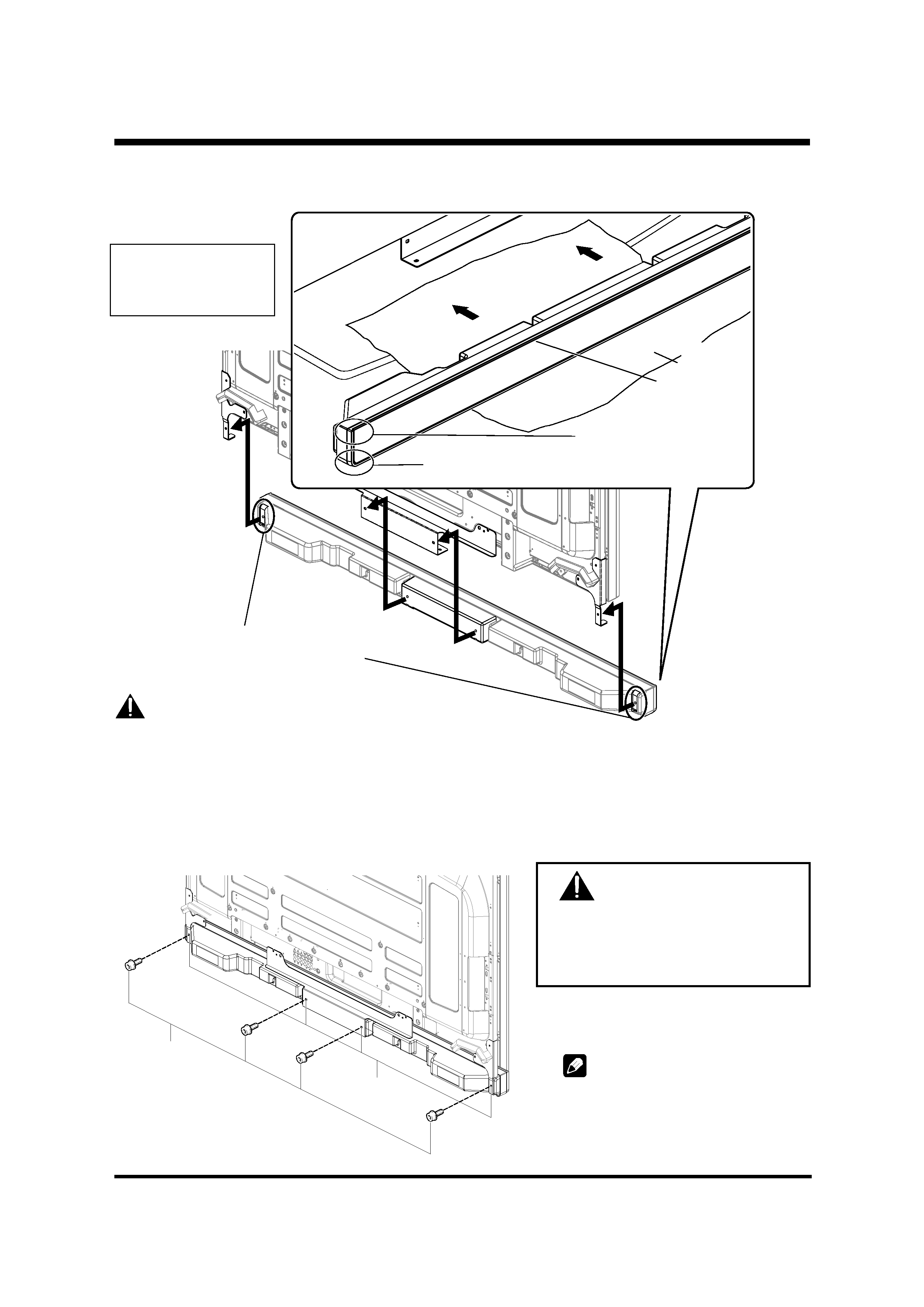
When installing the speaker, do not use any screws other
than those supplied, otherwise the speaker may come
off from the main unit and fall over.
·
When installing the speaker, tighten the screws firmly.
·
Please handle the speaker with sufficient care, as the
grille net and the cabinet can become damaged or broken
when they are subjected to strong external impacts.
·
Placing a CRT computer screen or CRT monitor near to
the speaker may result in interference or color distortion.
If this happens, distance the monitor from the speaker.
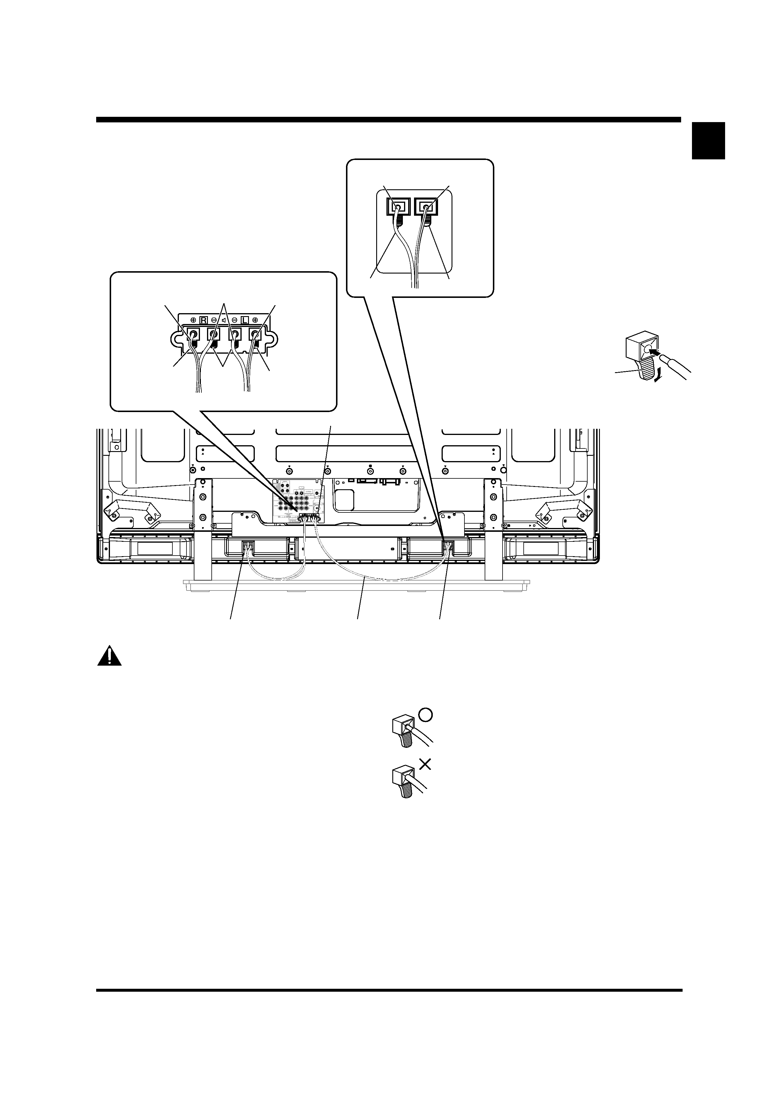
About the input
·
In order to prevent damage to the speaker system
resulting from input overload, please observe the
following precautions:
·
Do not use the speaker with anything other than the
specified Pioneer Plasma Display. Doing so may result in
damage or fire.
·
Be sure to turn the connected devices off and remove
the power cord from the wall outlet beforehand when
changing the connection or installation method.
·
When using a tone control function to greatly emphasize
treble sounds, do not use excessive amplifier volume.
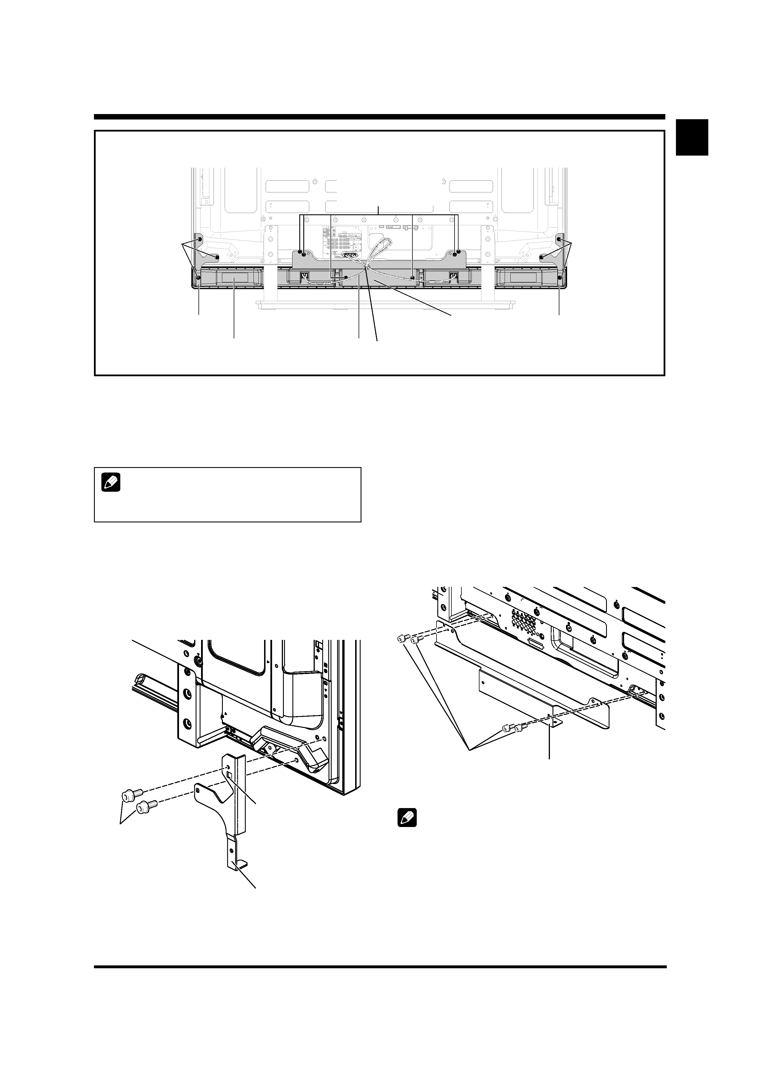
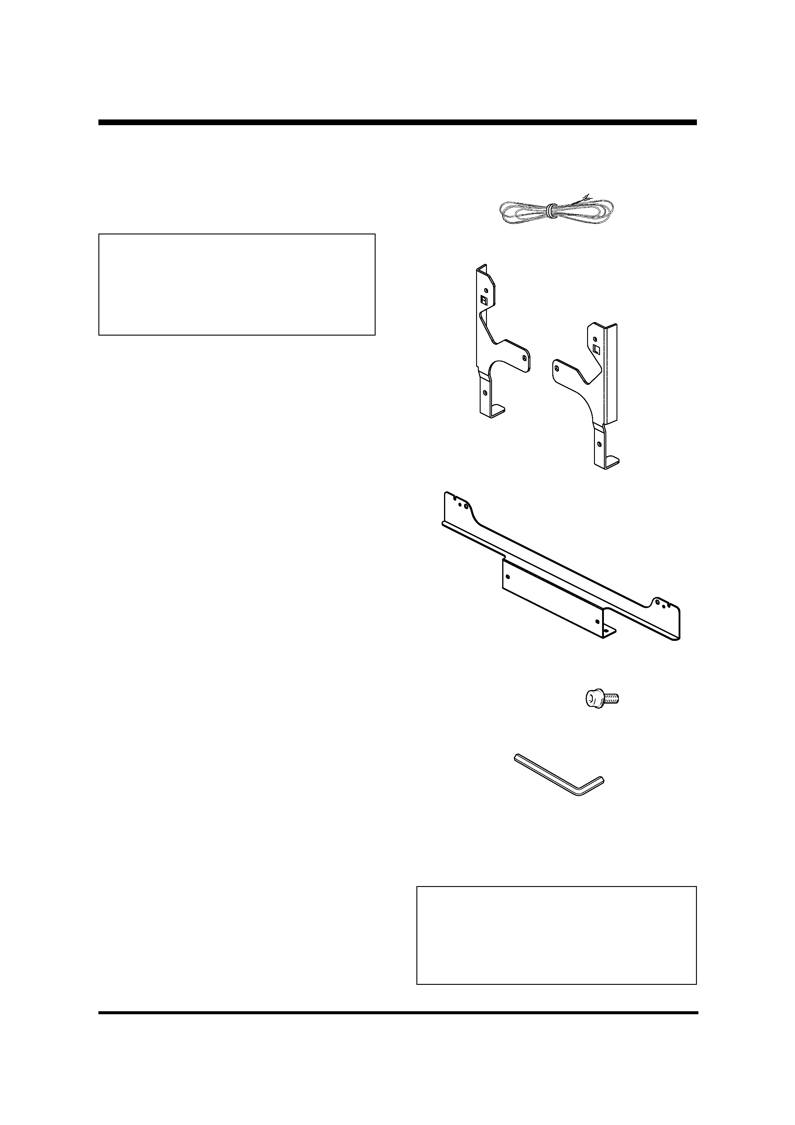
CHECKING THE ACCESSORIES
· Speaker Cable
× 2
· Speaker Mounting Fittings
Bracket, for Right and Left Sides
Bracket for Center
· Speaker Mounting Screw
(M5
× 10 mm : Black) × 12
· Hexagonal wrench
(Opposite side 4 mm for M5 use) x 1
· Operating Instructions
Installation
· Consult your dealer if you encounter any difficulties
with this installation.
· Pioneer is not liable for any damage resulting from
improper installation, improper use, modification, or
natural disasters.
background image
3
English
English
INSTALLATION ON THE PLASMA
DISPLAY
Perform installation according to the following steps 1 to 4.
NOTE:
Before attaching the speaker, please attach the table top
stand to the Plasma Display unit.
1. Attach the speaker mounting fittings to the
rear of the Plasma Display.
·
Attach the fittings for right and left sides to the bottom
right and left on the rear panel of the Plasma Display using
the supplied screws.
·
Tighten the two screws in the order 1 followed by 2.
Plasma Display with the speaker installed
Speaker
mounting
screw
(M5 x 10 mm)
Speaker mounting fitting
(right side)
Speaker cable
Speaker mounting
fitting (center)
Speaker
Speaker mounting
fitting (left side)
Speaker
mounting screw
(M5 x 10 mm)
2. Attach the center fitting to the lower center
on the rear panel of the Plasma Display.
·
Attach the center fitting to the lower center on the rear
panel of the Plasma Display using the four supplied
screws.
·
Tighten the four screws in the order 1, 2, 3, 4 as shown
in the drawing.
·
When fitting the screws, place screws 1 and 2 through
the holes in the center fitting, and align screws 3 and 4
with the cutaway slots in the center fitting.
NOTE:
·
See page 6 for speaker mounting procedures when using
the hung on wall unit.
Speaker mounting
screw (M5 x 10 mm)
Bead Band
(Accessories of the Plasma Display)
1
2
Speaker mounting
screw (M5 x 10 mm)
Label "L" is
affixed to the left
side fitting.
(Similarly, label
"R" is
affixed to the
right side fitting.)
Speaker mounting fitting for the
left side
(the fitting method is the same
as the fitting for the right side)
1
2
3
4
Speaker mounting
screw (M5 x 10 mm)
Speaker mounting fitting for
center
background image
English
4
CAUTION
If you want to move the Plasma Display unit,
make sure that you remove the speaker first.
In addition, do not move the display holding on
to the mounting fittings. This can result in injury
or damage to the unit.
For illustrative purposes,
the table top stand is not
presented here.
The upper side of the speaker
does not have a round corner.
The bottom side of the speaker has a round corner
when viewed from the front side of the Plasma Display.
3. Fit the speaker to the mounting fittings in the correct direction.
·
Be sure not to mount the speaker upside down.
Front side of
the speaker
The screw hole at the bottom surface of the
speaker mounting fitting is used when the
Plasma Display is installed on the wall. It is
not used when installed with the stand.
Caution
·
To avoid any damage to the speaker and/or table top stand from striking against each other, fit the speaker to the mounting
fittings while confirming their locations. As you may easily strike the stand, use the protective wrapping in which the speaker
was wrapped between the speaker and stand.
·
When the speaker mounting fittings do not fit the grooves at the rear of the speaker, adjust the speaker mounting fittings
angle.
4. Fix the speaker mounting fittings and the speaker with the supplied screws.
·
Fix the center part of the speaker first with the supplied screws, then fix the right and left sides alike.
·
Tighten the four screws in the order 1, 2, 3, 4 as shown in the drawing.
NOTE:
If after attaching the speaker its position
needs to be adjusted horizontally or vertically,
first loosen the speaker mounting screws,
reposition and then tighten the screws again
at the appropriate position.
Protective
wrapping
Insert the speaker
mounting fittings into the
grooves at the rear of the
speaker.
1
2
3
4
Speaker
mounting screw
(M5 x 10 mm)
Screw hole
background image
5
English
English
Black
Gray line
Gray line
White
Speaker terminal
Speaker terminal
Speaker cable
Speaker terminal
Lever
Red
·
Press the lever and insert the end of the
cable.
·
When you release the lever, it clamps onto
the speaker cable.
6. Connect the other end
of the speaker cables
to the speaker.
·
Connect the cables correctly with
respect to the polarity of the Plasma
Display and the speaker terminals,
that is,
cable to
terminals and
cable to
terminals. To do so,
connect the cable with the gray line
to the
terminals and the white
cable to the
terminals.
5. Connect the supplied speaker
cables to the back of Plasma
Display.
·
Connect the cables correctly with respect to the
polarity of the Plasma Display and the speaker
terminals, that is,
cable to
terminals and
cable to
terminals. To do so, connect the
cable with the gray line to the
terminals and
the white cable to the
terminals.
Caution
·
Be sure to turn the connected devices off and remove
the power cord from the wall outlet beforehand when
changing the connection or installation method.
·
If you insert the speaker cable too far so that the insulation
is touching the speaker terminal, you may not get any
sound. Please insert it with showing the copper wire.
·
Check if the end of the speaker cables are securely
connected to the terminals by slightly tugging on the cable
after making connections. Loose connections may result
in sound dropouts or noise.
·
If there is a short in the
and
cables caused by an
exposed lead wire, excessive load may be applied to the
Plasma Display, resulting in interrupted operation or
malfunction.
·
Incorrect connections of the speaker cable to the right or
left of the Plasma Display terminals with respect to the
polarity may result in insufficient stereo sound effects,
delivering poor bass sounds or unstable sound image.
·
Bundle the code without pulling the cord.
Red
Black
Red
Gray line
White

Reviews

There are no reviews of this manual yet.