ORDER NO.
PIONEER CORPORATION 4-1, Meguro 1-chome, Meguro-ku, Tokyo 153-8654, Japan
PIONEER ELECTRONICS (USA) INC. P.O. Box 1760, Long Beach, CA 90801-1760, U.S.A.
PIONEER EUROPE NV Haven 1087, Keetberglaan 1, 9120 Melsele, Belgium
PIONEER ELECTRONICS ASIACENTRE PTE. LTD. 253 Alexandra Road, #04-01, Singapore 159936
PIONEER CORPORATION 2001
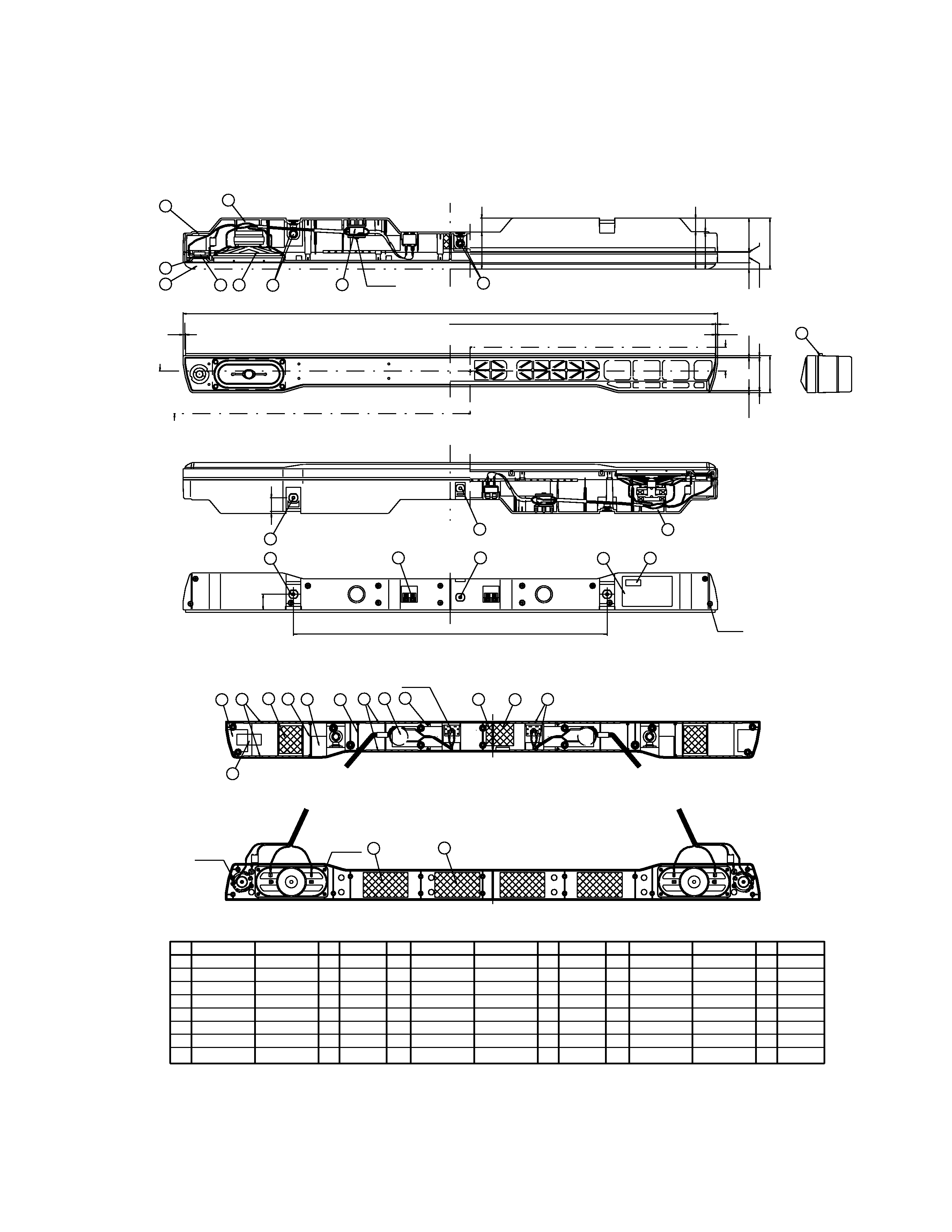
The speaker grille is attached to the baffle using 12 catches.
When removing, use a sharp pointed object, such as a plastic
board , or eyeleteer. Insert the point between the grille and
baffle, and gently prize the grille off. Alternatively, you can
remove the cabinet and the woofer unit, then push the grille out
from the inside.
Damage to the grille during removal may be unavoidable, but
be careful not to break the catches off of the baffle.
The woofer units are attached to the baffle by four screws from
the inside of the speaker cabinet. To remove the woofer units,
remove the four screws. When reattaching, make sure the large
connectors (attached to the speaker wire) are facing outward.
The tweeters are attached to the baffle by two screws from the
inside of the speaker cabinet. To remove the tweeter, remove
the two screws. When reattaching, make sure the larger connec-
tors are both facing inward. Also, the left cutout should be fac-
ing top left; the right cutout, bottom left.
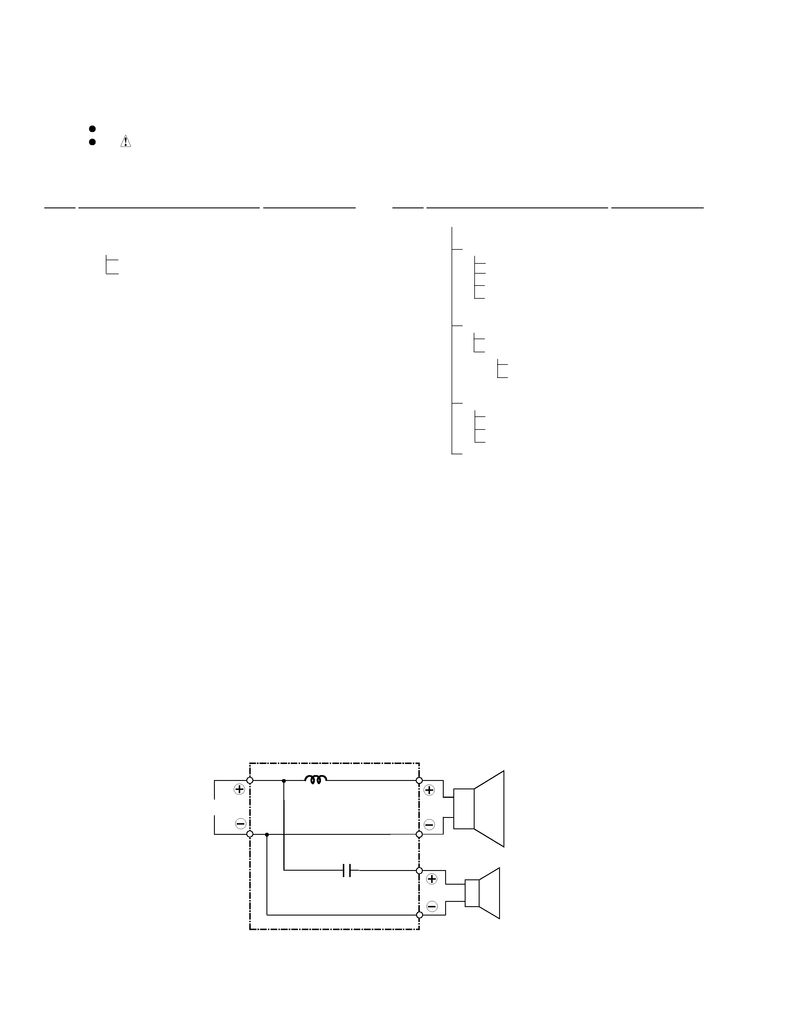
Network ASSY is attached from the inside using screws and
adhesive. To take out, remove the screw.
RRV2556
T-ZZB NOV. 2001 Printed in Japan
PDP-S08
SPEAKER SYSTEM
XIN/E
FOR PRECAUTION OF
REASSEMBLY AND DISASSEMBLY
65S
This service manual is intended for qualified service technicians; it is not meant for the
casual do-it-yourselfer. Qualified technicians have the necessary test equipment and
tools, and have been trained to properly and safely repair complex products such as
those covered by this manual.
Improperly performed repairs can adversely affect the safety and reliability
of the product and may void the warranty. If you are not qualified to perform the repair
of this product properly and safely, you should not risk trying to do so and refer the
repair to a qualified service technician.
WARNING
This product contains lead in solder and certain electrical parts contain chemicals
which are known to the state of California to cause cancer, birth defects or other
reproductive harm.
Health & Safety Code Section 25249.6 Proposition 65