ORDER NO.
PIONEER CORPORATION 4-1, Meguro 1-chome, Meguro-ku, Tokyo 153-8654, Japan
PIONEER ELECTRONICS (USA) INC. P.O. Box 1760, Long Beach, CA 90801-1760, U.S.A.
PIONEER EUROPE NV Haven 1087, Keetberglaan 1, 9120 Melsele, Belgium
PIONEER ELECTRONICS ASIACENTRE PTE. LTD. 253 Alexandra Road, #04-01, Singapore 159936
PIONEER CORPORATION 2006
ARP3368
T ZZY AUG. 2006 Printed in Japan
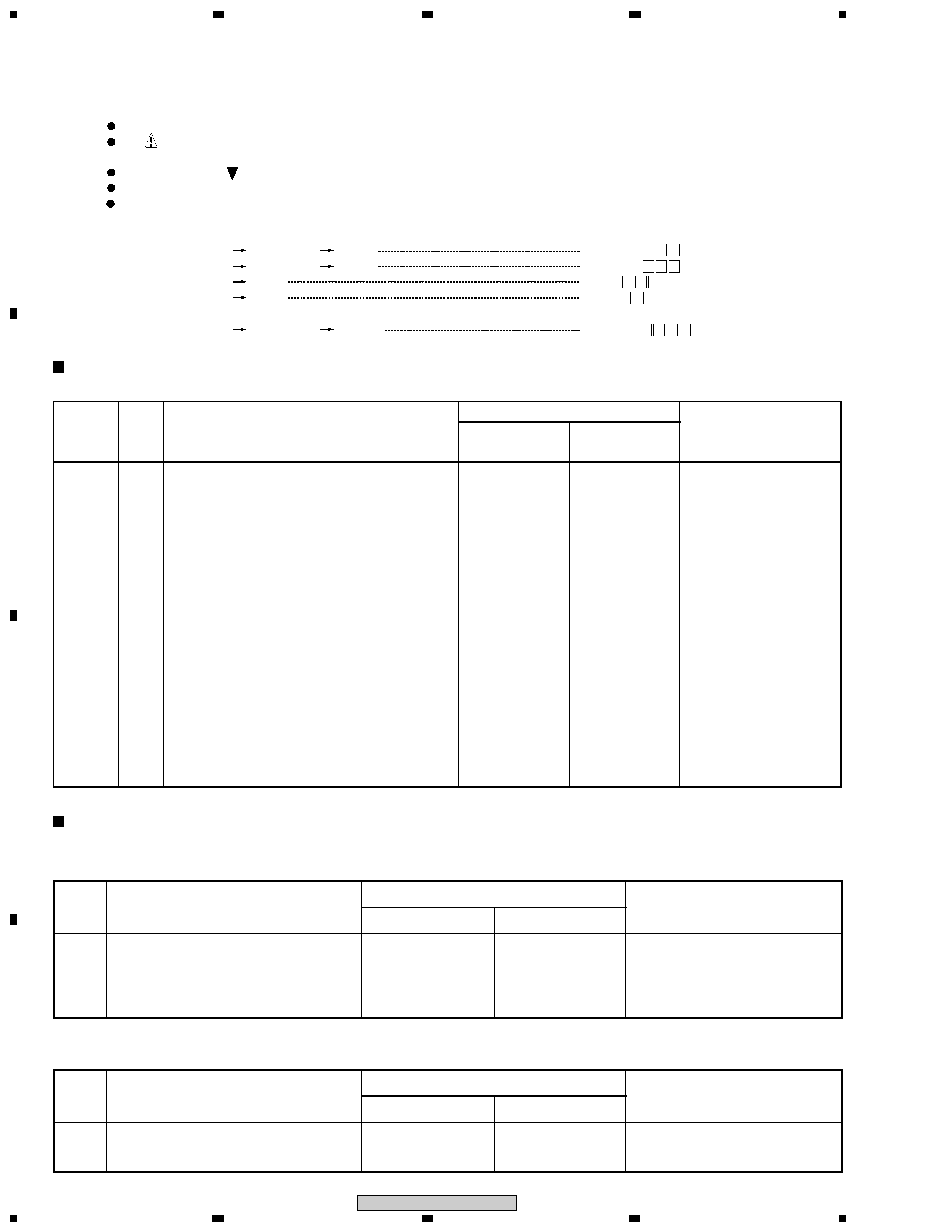
THIS MANUAL IS APPLICABLE TO THE FOLLOWING MODEL(S) AND TYPE(S).
Model
Type
Power Requirement
Serial No. (Please comfirm the figures)
PDP-42MXE10
DFK51
AC100 to 240V
&&&&500000&&
PDP-42MXE10
PLASMA DISPLAY
¶ This service manual should be used together with the following manual(s):
Model No.
Order No.
Remarks
PDP-425CMX/LUC5
ARP3340
SAFETY INFORMATION, EXPLODED VIEWS AND PARTS LIST, BLOCK DIAGRAM,
PCB PARTS LIST, ADJUSTMENT, IC INFORMATION etc.
ARP3341
SCHEMATIC DIAGRAM and PCB CONNECTION DIAGRAM
Narrow pitch connectors on that model are changed due to change of connector material.
Therefore there is no interchangeable to original parts.
Using incorrect parts to this model will cause some malfunction by Whisker.
![Cover page of PIONEER PDP-42MXE10-DFK51[1] Service Manual](images/products/15/67/15671F8F251CAAEE732B6AA0CAE8F7C1DA1AC559_1.jpg "Cover page of PIONEER PDP-42MXE10-DFK51[1] Service Manual")