PIONEER MMA-V700/Z/ES Service Manual

Cover page of PIONEER MMA-V700/Z/ES Service Manual

Service Manual for PIONEER MMA-V700/Z/ES, downloadable as a PDF file.

Manual details

  • Immediate download after payment.
  • Delivered as a PDF file.
  • The manual has 8 pages
  • File size: 0.25 MB
  • Available language versions: English
  • Different language versions may vary sligthly in file size and page count.

We guarantee that...

  • our manuals are complete,
  • the manual includes circuit diagrams,
  • our manuals are checked with antivirus,
  • We'll issue refund if the manual is damaged, incomplete or unreadable (our refund policy)

Sample pages

Thumbnail of page 1Thumbnail of page 2Thumbnail of page 3Thumbnail of page 4
Thumbnail of page 5Thumbnail of page 6Thumbnail of page 7Thumbnail of page 8
Thumbnail of page 9
background image
ORDER NO.
PIONEER ELECTRONIC CORPORATION 4-1, Meguro 1-Chome, Meguro-ku, Tokyo 153-8654, Japan
PIONEER ELECTRONICS SERVICE, INC. P.O. Box 1760, Long Beach, CA 90801-1760, U.S.A.
PIONEER ELECTRONIC (EUROPE) N.V. Haven 1087, Keetberglaan 1, 9120 Melsele, Belgium
PIONEER ELECTRONICS ASIACENTRE PTE. LTD. 501 Orchard Road, #10-00 Wheelock Place, Singapore 238880
PIONEER ELECTRONIC CORPORATION 1998
c
MMA-V700
TRT1122
1. EXPLODED VIEWS AND PARTS LIST ................ 2
2. SCHEMATIC DIAGRAM ....................................... 4
3. PCB CONNECTION DIAGRAM ............................ 6
4. PCB PARTS LIST ................................................. 7
5. PANEL FACILITIES AND SPECIFICATIONS ....... 8
CONTENTS
O ­ IZC SEPT. 1998 Printed in Japan
Type
Model
Power Requirement
Remarks
MMA-V700
Z/ES
DC 12V
THIS MANUAL IS APPLICABLE TO THE FOLLOWING MODEL(S) AND TYPE(S).
MIC AMPLIFIER
background image
2
MMA-V700
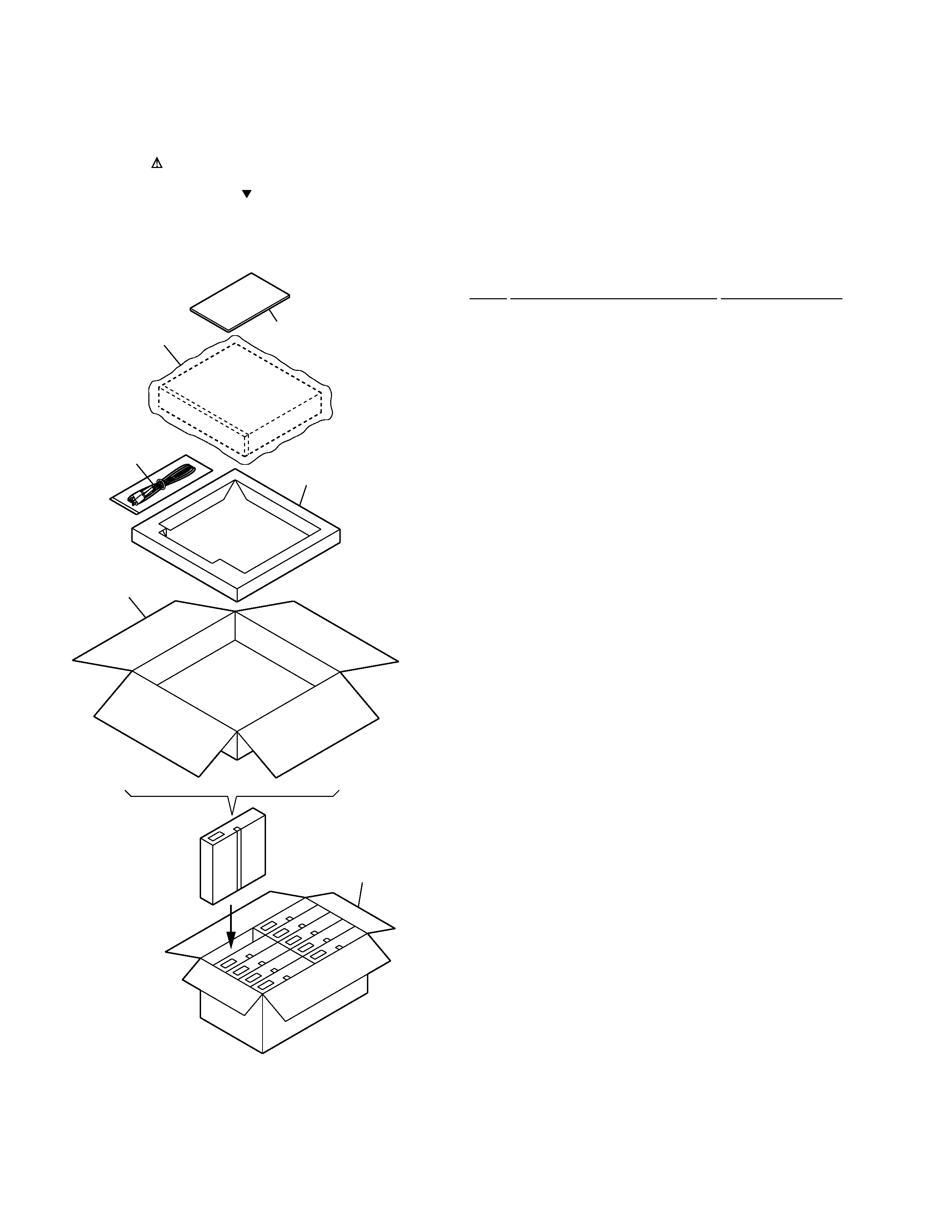
1.1 PACKING
· PACKING PARTS LIST
Mark No.
Description
Part No.
1. EXPLODED VIEWS AND PARTS LIST
NOTES:
· Parts marked by "NSP" are generally unavailable because they are not in our Master Spare Parts List.
· The mark found on some component parts indicates the importance of the safety factor of the part.
Therefore, when replacing, be sure to use parts of identical designation.
· Screws adjacent to mark on the product are used for disassembly.
1
2
3
6
4
5
1
Microphone Output Cable
MDE1066
2
Operating Instructions
MRB1026
(English/Chinese)
3
Packing Case
MHG1206
4
Inner Partition
MHG1207
5
Mirror Mat Sheet
MHL1021
6
Master Carton
MHP1095
background image
3
MMA-V700
1
2
12
12
3
Including VR1 and VR2
on the MAIN BOARD Assy.
4
4
5
6
7
10
11
8
9
10
10
10
VR1
VR2
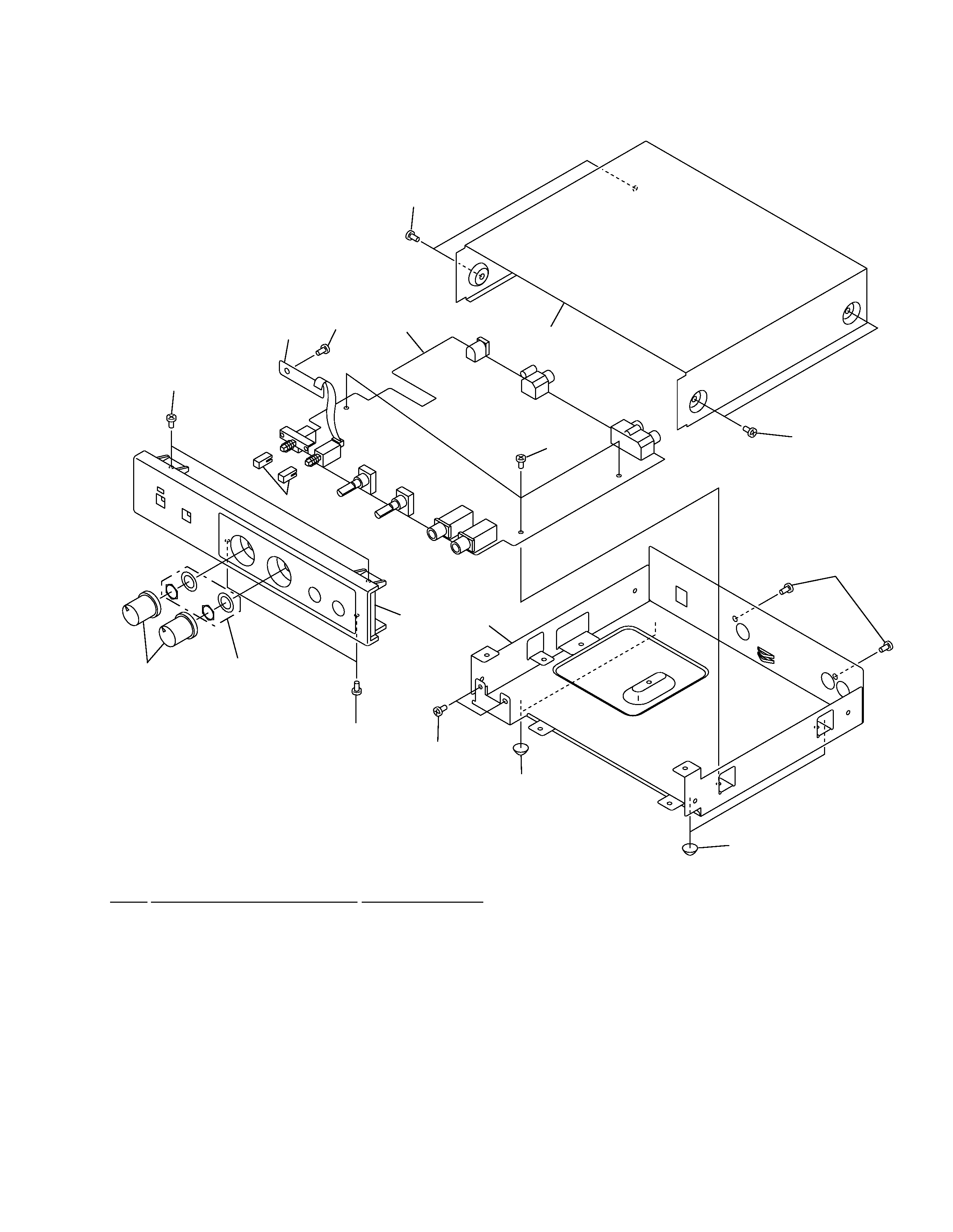
1
MAIN Board Assy
MWX1089
NSP
2
LED Board Assy
MWX1090
3
Rotary Knob
AAB1063
4
Foot
MEP1043
5
Bonnet
MNA1065
6
Chassis
MNA1117
7
Panel
MNK1279
8
Button
MNK3082
9
Screw
BBZ30P060FMC
10
Screw
BBZ30P060FZK
11
Screw
BMZ30P060FMC
12
Screw
BPZ30P080FZK
1.2 MAIN SECTION
· MAIN SECTION PARTS LIST
Mark No.
Description
Part No.
background image
MMA-V700
4
A
B
C
D
1
23
4
12
3
4
A
C10
2200p
R12
33k
R22
33k
GND
JA1
MKN1004
R10
470
C11
4.7/50
R11
56k
R14
330
C13
22/16
R24
330
C23
22/16
TP1
MAIN BOARD ASSY
(MWX1089)
TP2
GND GND
1/2
GND
+9V
GND
C56
22/16
C14
10/50
R15
1k
R16
2.2k
VR1
MCS1007
MIC 1
VOLUME
R59
1k
C24
10/50
R25
1k
R26
2.2k
VR2
MCS1007
MIC 2
VOLUME
R60
1k
R13
6.8k
C12
330p
IC1
M5218AL
GND
GND
C30
1000p
GND
GND GND
1/2
GND
+9V
GND
GND
GND
GND
C20
2200p
GND
GND GND
2/2
GND
GND
MIC1
JA2
MKN1004
R20
470
C21
4.7/50
R21
56k
TP3
TP4
MIC2
JA3 (1/2)
MKN1021
R30
1k
C31
10/50
R32
10k
R31
100k
TP5
TP6
LINE IN
3
2
8
4
1
IC2
M5218AL
C57
22/16
R33
10k
C32
220p
C33
4.7/50
R37
1k
R35
10k
R34
47k
R57
620
R58
620
Q1
2SD2144S
3
2
8
4
1
IC1
M5218AL
R23
6.8k
C22
330p
5
6
7
1
4
2
1
4
2
A
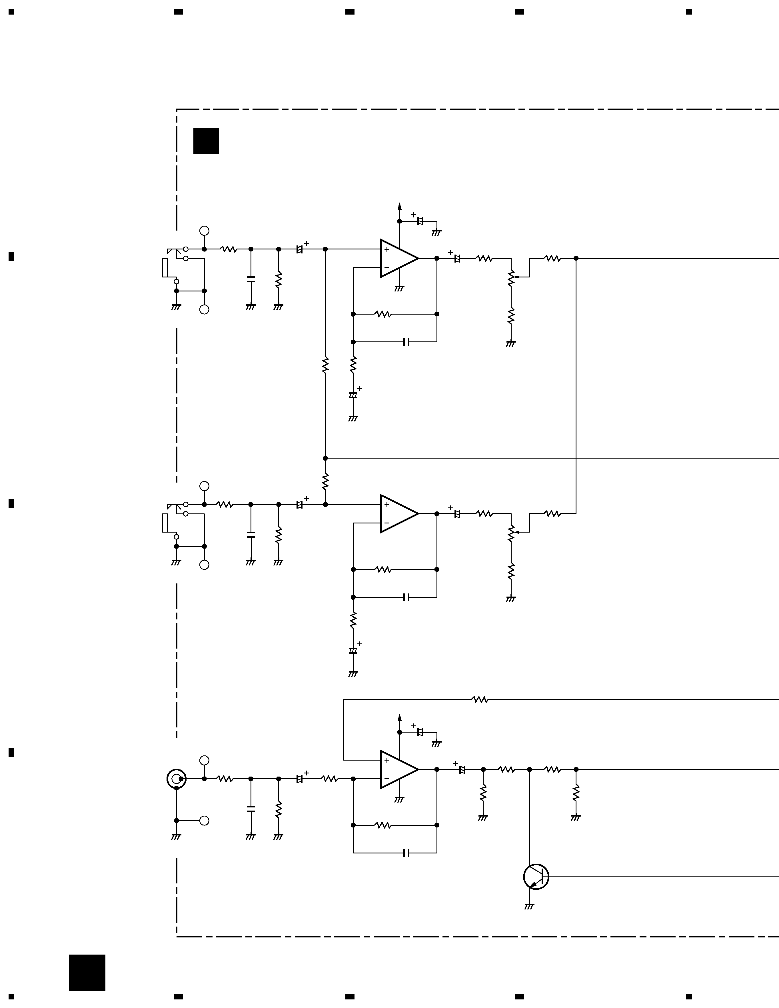
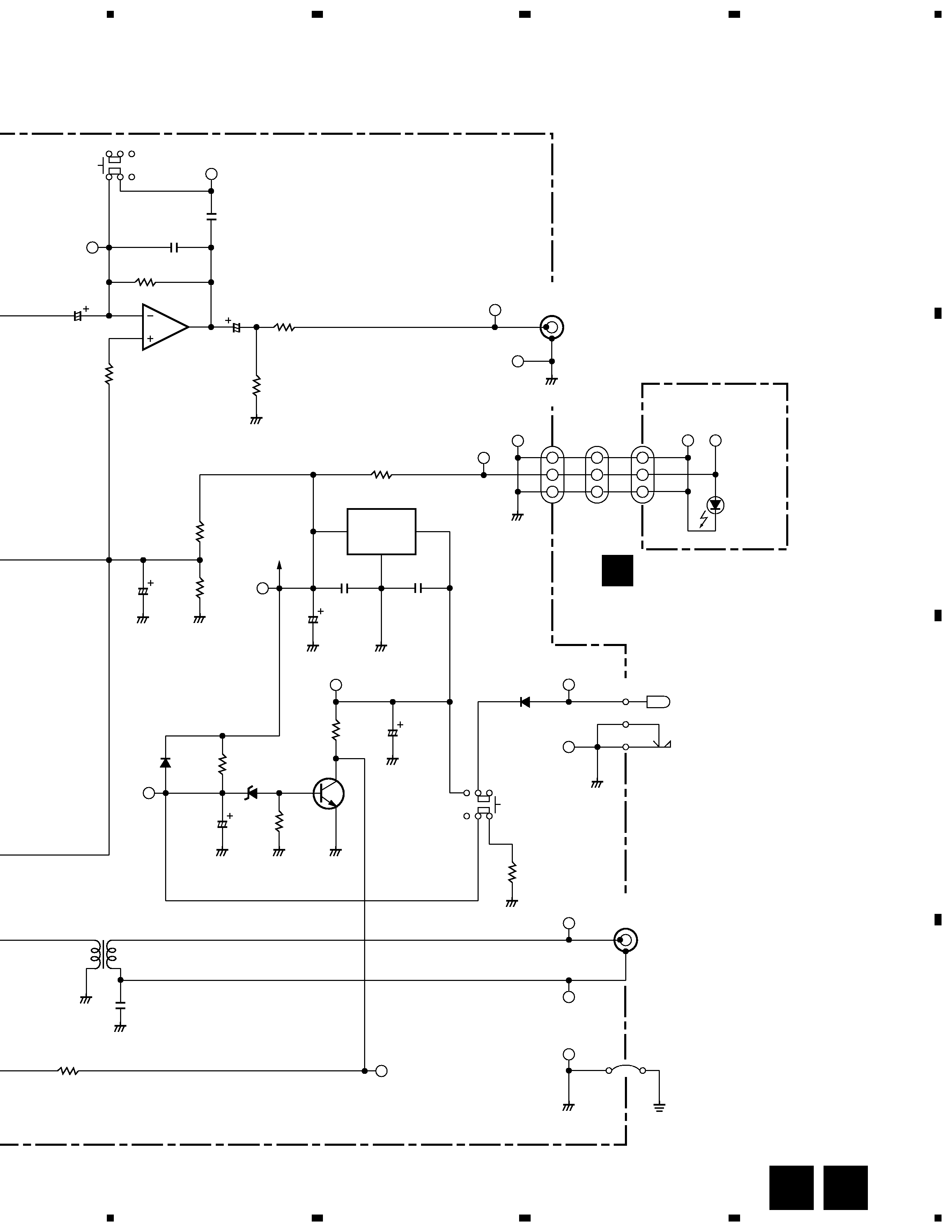
2. SCHEMATIC DIAGRAM
background image
MMA-V700
5
A
B
C
D
5
67
8
5
6
7
8
Note : When ordering service parts, be sure to refer to "EXPLODED VIEWS and PARTS LIST" or "PCB PARTS LIST".
R38
1k
C34
4.7/50
C35
150p
SW2
MSG1011
C36
470p
TP22
TP23
C50
100/16
R51
10k
R50
10k
GND
GND
1
24
3
GND
2/2
GND
GND
GND
GND
GND
1
2
3
1
2
3
1
2
3
OUT
COM
IN
GND
GND
GND
GND
GND
IC2
M5218AL
C37
10/50
R41
100
R52
330
R40
47k
R39
13k
6
1
4
2
5
3
6
5
7
T1
MTT1021
R36
2.2k
C54
0.1
+9V
TP15
IC3
NJM78M09FA
C59
0.1
TP16
TP20
D2
RD6R2JS
Q2
2SC2458
C58
0.1
C51
470/16
R55
10k
D1
1SS133
R53
47k
C52
33/16
R54
220k
C53
1000
/25
13
2
TP21
TP9
TP10
JA3 (2/2)
MKN1021
LINE OUT
AC ADAPTER
DC IN 12V
TP11
TP12
MDD3006
SW1
MSG1006
6
3
5
2
4
1
1
3
2
GND
R56
100
TP17
TP18
D3
ERA15-02VH
GND
JA4
MKN1023
JA6
MKN1019
J1
MKX1007
TP7
TP8
TP19
MIC
MIX OUT
GND
FG
LED BOARD ASSY
(MWX1090)
TP14
TP13
D4
TLG208
(POWER)
B
SWITCHES
SW1: POWER
SW2: FREQUENCY BOOSTER
CN1
MKP1021
B
A

Reviews

There are no reviews of this manual yet.