PIONEER MJ-L77/MYXK Service Manual

Cover page of PIONEER MJ-L77/MYXK Service Manual

Service Manual for PIONEER MJ-L77/MYXK, downloadable as a PDF file.

We also have owner's manual to this model.

Manual details

  • Immediate download after payment.
  • Delivered as a PDF file.
  • The manual has 62 pages
  • File size: 3.89 MB
  • Available language versions: English
  • Different language versions may vary sligthly in file size and page count.

We guarantee that...

  • our manuals are complete,
  • the manual includes circuit diagrams,
  • our manuals are checked with antivirus,
  • We'll issue refund if the manual is damaged, incomplete or unreadable (our refund policy)

Sample pages

Thumbnail of page 1Thumbnail of page 2Thumbnail of page 3Thumbnail of page 4
Thumbnail of page 5Thumbnail of page 6Thumbnail of page 7Thumbnail of page 8
Thumbnail of page 9
background image
ORDER NO.
PIONEER CORPORATION 4-1, Meguro 1-chome, Meguro-ku, Tokyo 153-8654, Japan
PIONEER ELECTRONICS SERVICE, INC. P.O. Box 1760, Long Beach, CA 90801-1760, U.S.A.
PIONEER ELECTRONIC (EUROPE) N.V. Haven 1087, Keetberglaan 1, 9120 Melsele, Belgium
PIONEER ELECTRONICS ASIACENTRE PTE. LTD. 253 Alexandra Road, #04-01, Singapore 159936
PIONEER CORPORATION 1999
c
MJ-L77
RRV2201
1. SAFETY INFORMATION ...................................... 2
2. EXPLODED VIEWS AND PARTS LIST ............... 3
3. BLOCK DIAGRAM AND SCHEMATIC DIAGRAM ..... 8
4. PCB CONNECTION DIAGRAM ......................... 22
5. PCB PARTS LIST ............................................... 29
6. ADJUSTMENT .................................................... 32
CONTENTS
7. GENERAL INFORMATION ................................ 43
7.1 DIAGNOSIS .................................................. 43
7.1.1 TROUBLESHOOTING ........................... 43
7.1.2 DISASSEMBLY ...................................... 46
7.2 IC .................................................................. 49
8. PANEL FACILITIES AND SPECIFICATIONS ....... 59
T ­ ZZE AUG. 1999 Printed in Japan
MINIDISC RECORDER
Type
Model
Power Requirement
Remarks
MJ-L77
MYXK
AC220-230V
NVXK
AC230V
THIS MANUAL IS APPLICABLE TO THE FOLLOWING MODEL(S) AND TYPE(S).
Component
Model
Service manual
Remarks
STEREO CD RECEIVER
XC-L77
RRV2187
S-L9-LRW
­­
­­
RRV2176
SPEAKER SYSTEM
­­
S-L9-A-LRW
­­
RRV2176
­­
­­
S-L8-LRW
RRV2178
STEREO CASSETTE DECK
CT-L77
RRV2199
MINIDISC RECORDER
MJ-L77
RRV2201
This manual.
÷ These products are component of systems. This product does not operate normally by
itself.
Please connect it to the STEREO CD RECEIVER XC-L77 and the DISPLAY UNIT DU-L77, an
accessory of the XC-L77, for adjustment and operation inspection.
^
)
MINIDISC
background image
MJ-L77
2
IMPORTANT
THIS PIONEER APPARATUS CONTAINS
LASER OF CLASS 1.
SERVICING OPERATION OF THE APPARATUS
SHOULD BE DONE BY A SPECIALLY
INSTRUTED PERSON.
LASER DIODE CHARACTERISTICS
MAXIMUM OUTPUT POWER: 32 mW
WAVELENGTH: 785 nm
Control method of the current through a laser diode.
The resistor R105 on the CORE MAIN UNIT ASSY (For MD
mechanism assy) are for the limiting of current through a laser
diode.
Control method of the laser output power
The laser pickup assy provide the photo-diodes and APC (Auto
Power Control) circuit.
The photo-diode detect output of the laser diode then IC104 control
the APC circuit according to the signal voltage of the photo-diode via
IC101.
The Variable resistancer on the FPC in the Laser pickup assy can
be adjusted the output level of Laser diode to fix the rated output
level.
Laser Interlock Switch
The loading position detect switch S101 is set to " LOAD ON " (ON:
low level, OFF: high level) position, IC104 get the " LOAD " signal,
and hand the laser " LDON " signal to No. 9 terminal (LDON) of the
Laser pickup assy.
Then a laser diode can be lighted exept when the level of signal
"LOAD " is low.
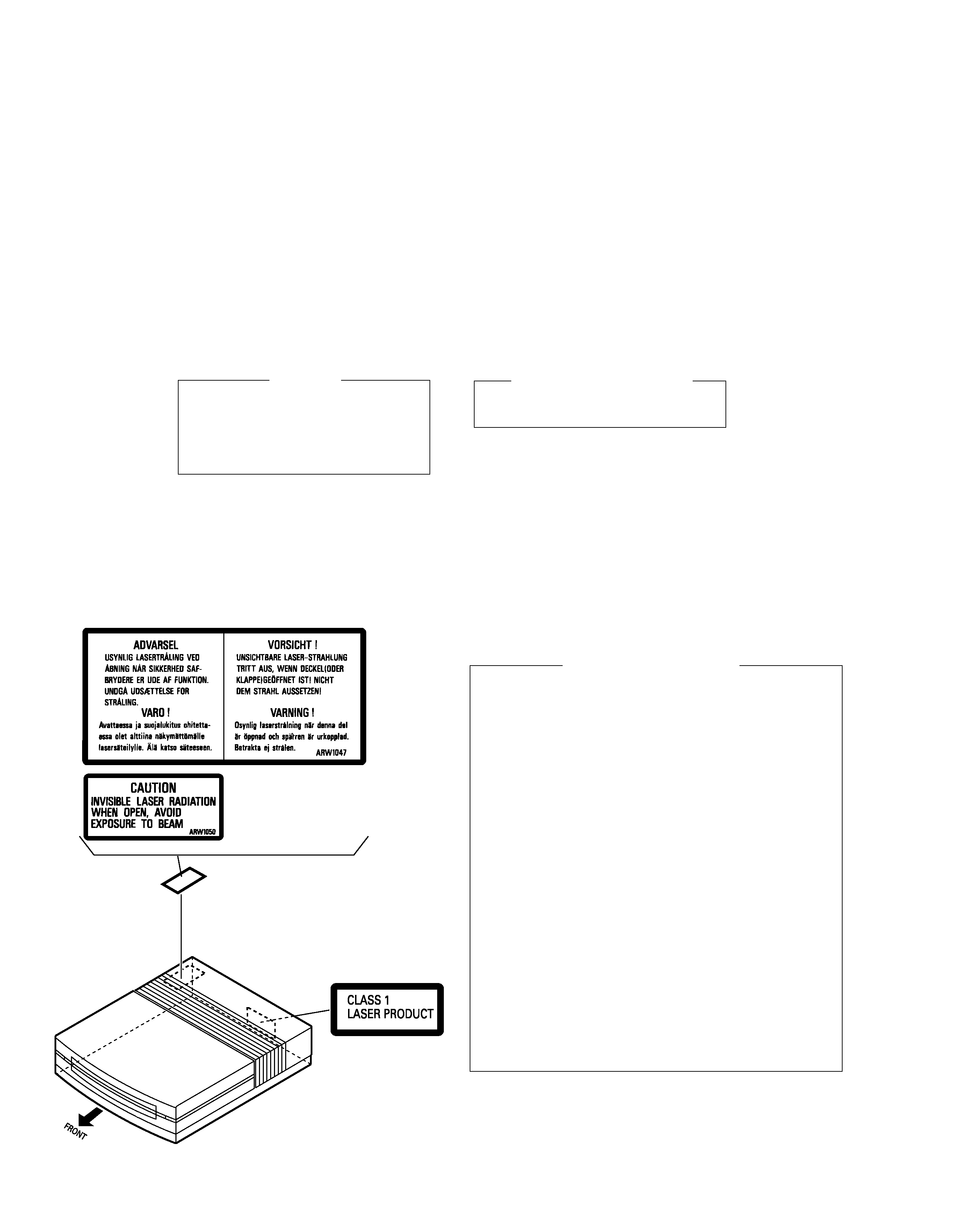
Additional Laser Caution
1. SAFETY INFORMATION
This service manual is intended for qualified service technicians; it is not meant for the casual
do-it-yourselfer. Qualified technicians have the necessary test equipment and tools, and have been
trained to properly and safely repair complex products such as those covered by this manual.
Improperly performed repairs can adversely affect the safety and reliability of the product and may
void the warranty. If you are not qualified to perform the repair of this product properly and safely, you
should not risk trying to do so and refer the repair to a qualified service technician.
WARNING
This product contains lead in solder and certain electrical parts contain chemicals which are known to the state of California to
cause cancer, bir th defects or other reproductive harm.
Health & Safety Code Section 25249.6 ­ Proposition 65
Refer to page 33.
LABEL CHECK
NVXK type
MYXK type
(Printed on the Rear Panel)
background image
MJ-L77
3
2. EXPLODED VIEWS AND PARTS LIST
NOTES :
Parts marked by " NSP " are generally unavailable because they are not in our Master Spare Parts List.
The
mark found on some component parts indicates the importance of the safety factor of the part.
Therefore, when replacing, be sure to use parts of identical designation.
Screw adjacent to
mark on the product are used for disassembly.
2.1 PACKING
Mark
MYXK type
NVXK type
(2) CONTRAST TABLE
MJ-L77/MYXK and NVXK are constructed the same except for the following:
1
Power Cord
ADG7010
ADG7009
3
Operating Instructions
ARC7251
Not used
(Swedish/Dutch/Portuguese/Spanish)
4
Operating Instructions
ARE7222
Not used
(French/English/Italian/German)
5
Operating Instructions (English)
Not used
ARB7196
9
Packing Case
AHD7769
AHD7801
11
Sub Packing
Not used
AHD7770
12
Fuse (5A)
Not used
AEK7001
Part No.
Remarks
Symbol and Description
No.
1
12
11
NVXK type only
3
4
5
13
10
9
8(1/2)
2
8(2/2)
7(2/2)
7(1/2)
MYXK type
only
MYXK type
only
MYXK type
only
NVXK type
only
6
1
Mark No.
Description
Part No.
(1) PACKING PARTS LIST
1
Power Cord
See Contrast table (2)
NSP
2
Warranty Card
ARY7022
3
Operating Instructions
See Contrast table (2)
4
Operating Instructions
See Contrast table (2)
5
Operating Instructions
See Contrast table (2)
6
Optical Digital Cord (L= 0.5m)
RKX1031
7
Pad Front
AHA7260
8
Pad Rear
AHA7261
9
Packing Case
See Contrast table (2)
10
Sheet (750
× 600 × 0.5)
Z23­007
11
Sub Packing
See Contrast table (2)
12
Fuse (5A)
See Contrast table (2)
13
Polyethylene Bag
Z21­038
(0.03
× 230 × 340)
background image
MJ-L77
4
A
B
D
D
B
C
C
A
24
3
18
2
31
16
38
1
34
12
37
11
11
11
11
17
4
27
29
32-2
21
39
8
32-1
6
36
7
34
39
37
20
30
22
21
5
28
13
15
34
10
34
9
26
35
14
35
25
25
23
35
38
38
38
38
13
Refer to "2.3 MD
MECHANISM ASSY".
2.2 EXTERIOR
background image
MJ-L77
5
Mark No.
Description
Part No.
(1) EXTERIOR PARTS LIST
Mark No.
Description
Part No.
1
AF UNIT ASSY
AWU7397
2
KEYR UNIT ASSY
AWU7398
3
KEYL UNIT ASSY
AWU7399
4
BLUE IND. UNIT ASSY
AWU7400
5
MAIN UNIT ASSY
AWU7395
6
TRANS. UNIT ASSY
AWU7396
7
30P FFC/30V
ADD7097
8
Cord with Plug
ADE7043
9
Power Transformer
ATT7054
10
Fuse (T200mA)
AEK1047
11
Float Rubber
REB1328
NSP
12
MD Mechanism Assy
RXA1777
13
Leg
AEB7090
14
Rear Panel
See Contrast table (2)
NSP
15
Bottom Plate
ANF7016
NSP
16
Top Plate
ANF7017
17
MD Base
ANG7191
18
MD Shield
ANG7192
19
· · · · · · · ·
20
MD Flap
AAN7190
21
Main Line
AAP7058
22
Sub Line
AAP7060
23
Sub Panel
AAP7061
24
Flap Plate
AAP7062
25
Front Line
AAP7066
26
CL Lens
AAX7704
27
MD Spring
ABH7154
28
Bottom Base
AMA7014
29
Bonnet
AMA7015
30
Button Assy A
AWL7044
31
Button Assy B
AWL7045
32
Top Panel Assy
AWL7052
NSP
32-1
Top Panel 1
AMB7645
NSP
32-2
Top Panel 2
AMB7646
33
· · · · · · · ·
34
Screw
BBT30P060FZK
35
Screw
BBZ30P060FMC
36
Screw
BBZ40P060FMC
37
Float Screw
RBA1133
38
Screw
VPZ30P080FZK
39
MD Spacer
AEB7181
NSP
40
Caution Label
See Contrast table (2)
Mark
MYXK type
NVXK type
(2) CONTRAST TABLE
MJ-L77/MYXK and NVXK are constructed the same except for the following:
14
Rear Panel
ANC7828
ANC7830
NSP
40
Caution Label
ARW1047
ARW1050
Part No.
Remarks
Symbol and Description
No.

Reviews

There are no reviews of this manual yet.