ORDER NO.
PIONEER CORPORATION 4-1, Meguro 1-chome, Meguro-ku, Tokyo 153-8654, Japan
PIONEER ELECTRONICS SERVICE, INC. P.O. Box 1760, Long Beach, CA 90801-1760, U.S.A.
PIONEER ELECTRONIC NV Haven 1087, Keetberglaan 1, 9120 Melsele, Belgium
PIONEER ELECTRONICS ASIACENTRE PTE. LTD. 253 Alexandra Road, #04-01, Singapore 159936
PIONEER CORPORATION 2001
c
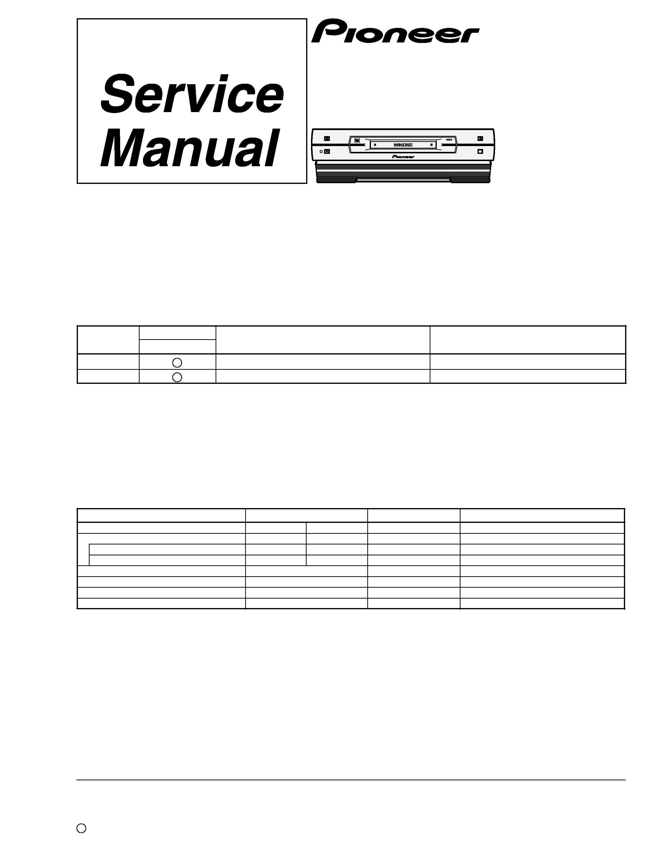
MJ-L11
RRV2472
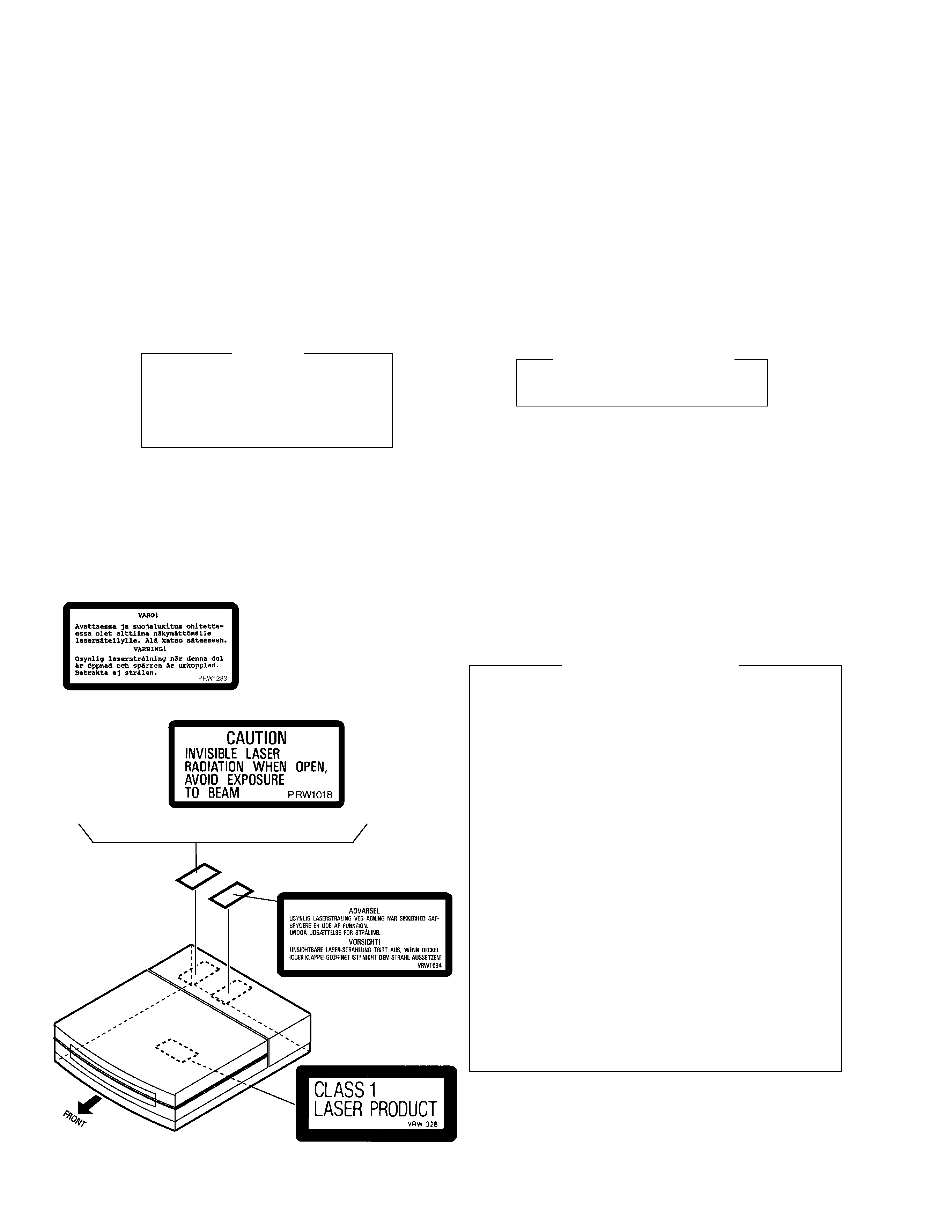
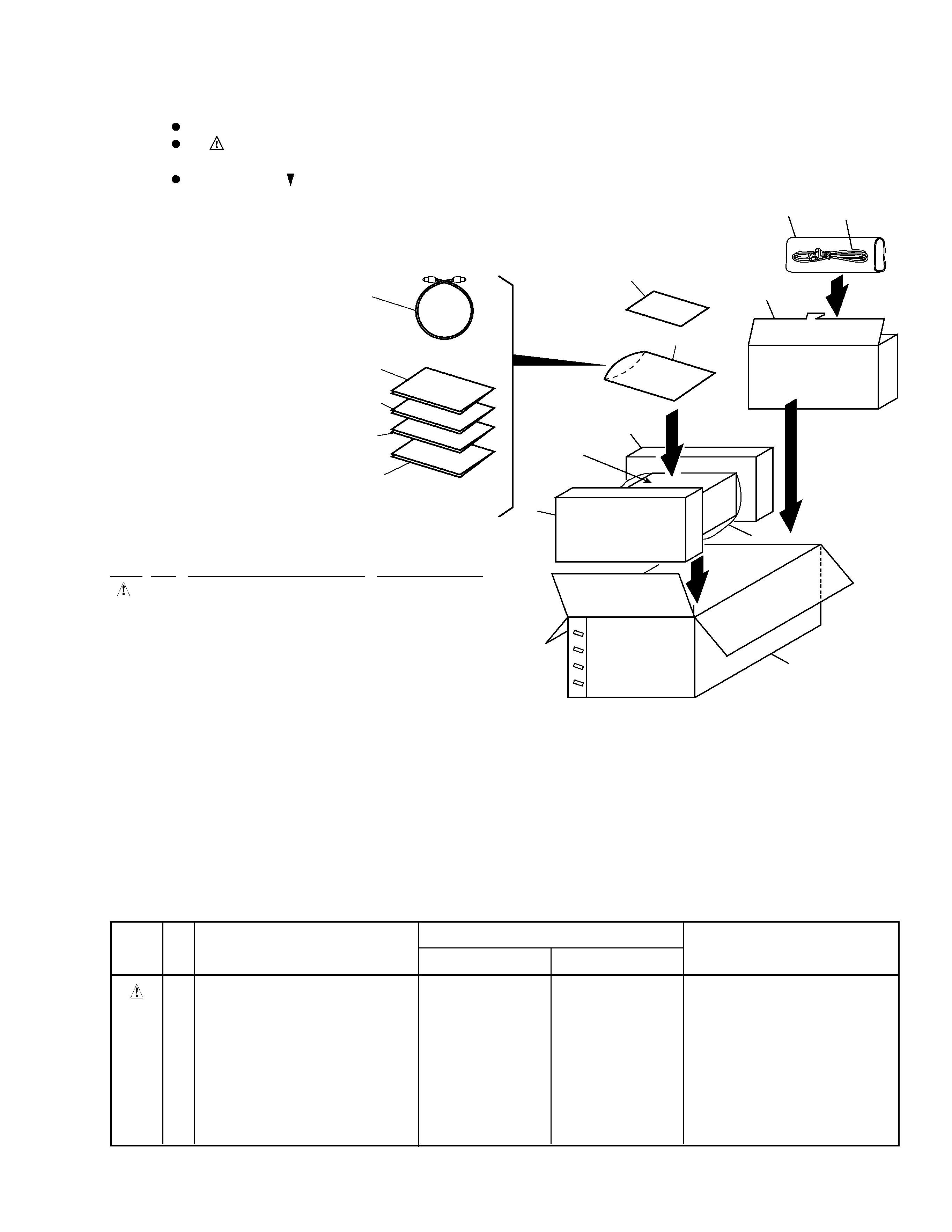
1. SAFETY INFORMATION ...................................... 2
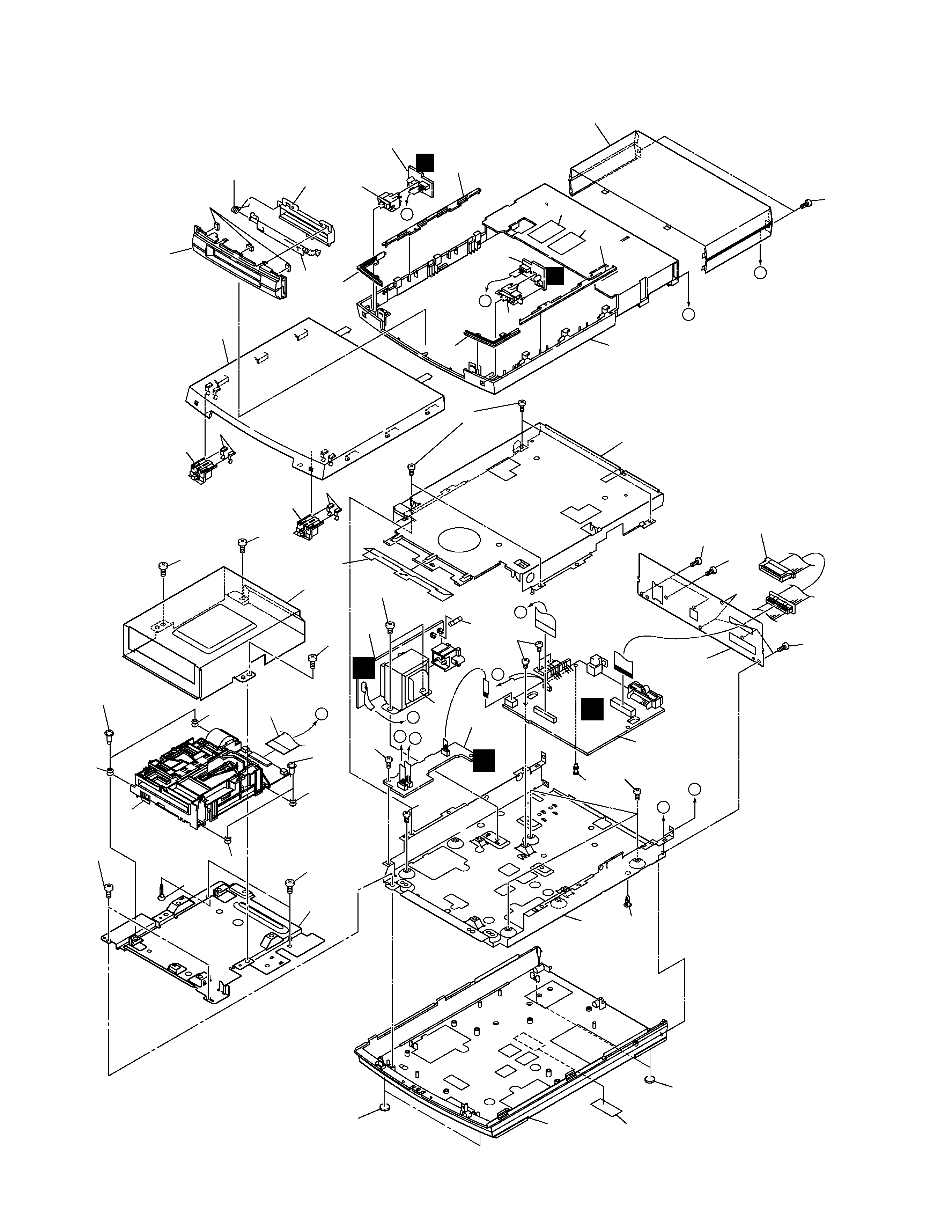
2. EXPLODED VIEWS AND PARTS LIST ............... 3
3. BLOCK DIAGRAM AND SCHEMATIC DIAGRAM ..... 8
4. PCB CONNECTION DIAGRAM ......................... 22
5. PCB PARTS LIST ............................................... 28
6. ADJUSTMENT .................................................... 31
CONTENTS
7. GENERAL INFORMATION ................................ 39
7.1 DIAGNOSIS .................................................. 39
7.1.1 SINGLE OPERAION MODE ................... 39
7.1.2 POWER ON SEQUENCE ...................... 40
7.1.3 DISASSEMBLY ...................................... 42
7.2 IC .................................................................. 46
8. PANEL FACILITIES AND SPECIFICATIONS ....... 49
T ZZR JUNE 2001 Printed in Japan
MINIDISC RECORDER
Type
Model
Power Requirement
Remarks
MJ-L11
MYXJ
AC220-230V
NVXJ
AC230V
THIS MANUAL IS APPLICABLE TO THE FOLLOWING MODEL(S) AND TYPE(S).
PLAY/PAUSE
REC
6
EJECT
STOP
0
7
¶ This product is a system(s) component.
This product does not function properly independently ; to avoid malfunctions, be
sure to connect it to the prescribed system component(s), otherwise damage may
result.
¶ Please connect it to the POWERED SUBWOOFER S-DV88SW or S-DV77SW, for
adjustment and operation inspection.
¶ Please connect it to the STEREO CD TUNER XC-L11 and the POWER STEREO
AMPLIFIER M-L11, for adjustment and operation inspection.
Component
Model
Service manual
Remarks
DVD/CD TUNER
XV-DV88
XV-DV77
RRV2480
SPEAKER SYSTEM
S-DV77
RRV2473
SATELLITE SPEAKER
S-DV88ST
S-DV77ST
RRV2486, RRV2473
POWERED SUBWOOFER
S-DV88SW
S-DV77SW
RRV2474, RRV2473
STEREO CD TUNER
XC-L11
RRV2470
STEREO POWER AMPLIFIER
M-L11
RRV2479
MINIDISC RECORDER
MJ-L11
RRV2472
This manual.
STEREO CASSETTE DECK
CT-L11
RRV2471
System option