3
KRP-M01
5
6
7
8
5
6
7
8
A
B
C
D
E
F
CONTENTS
10. SCHEMATIC DIAGRAM ...................................................................................................................................................... 4
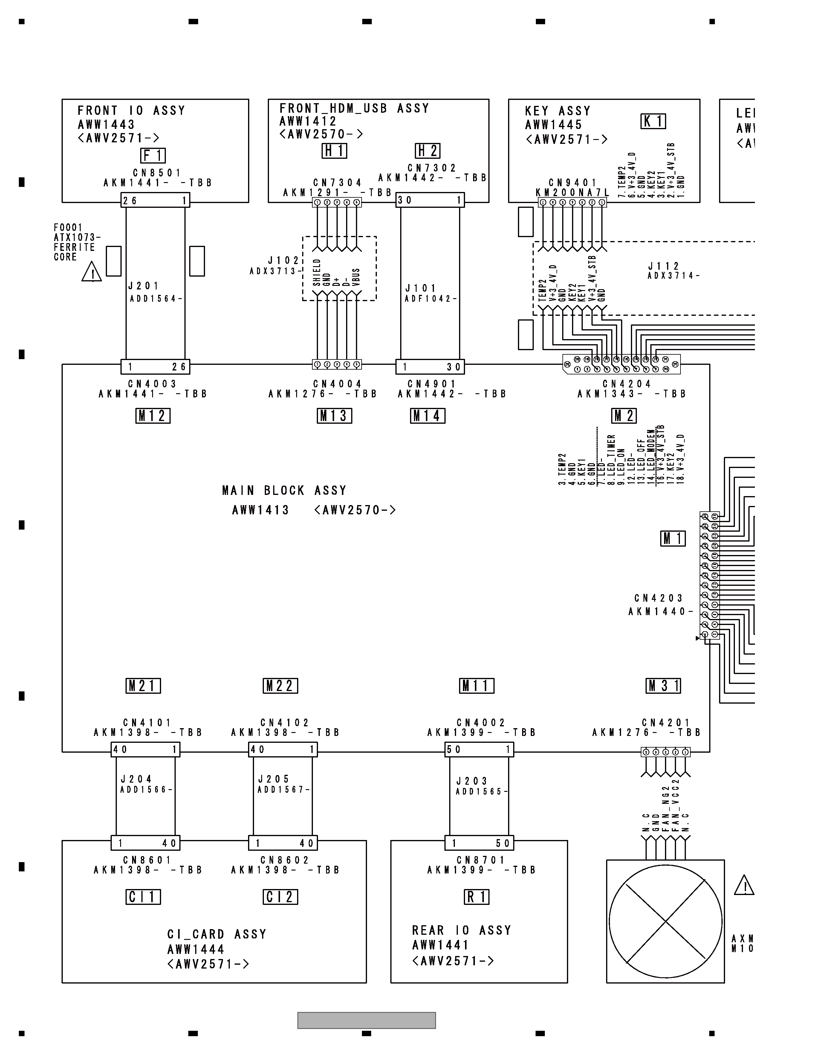
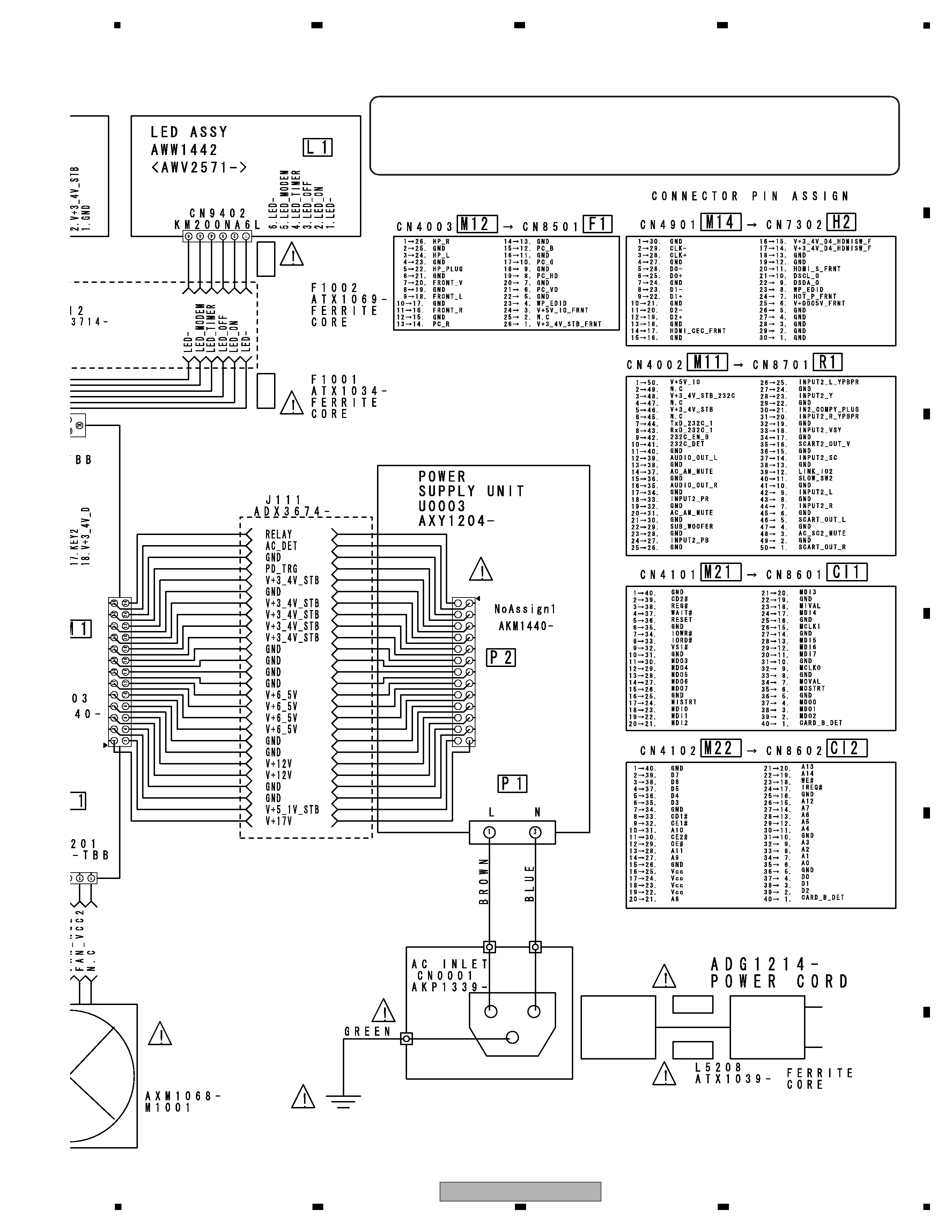
10.1 OVERALL CONNECTION DIAGRAM........................................................................................................................... 4
10.2 MAIN BLOCK ASSY (1/33) [BOARD_IF_0 BLOCK] .................................................................................................... 6
10.3 MAIN BLOCK ASSY (2/33) [BOARD_IF_1 BLOCK] .................................................................................................... 8
10.4 MAIN BLOCK ASSY (3/33) [BOARD_IF_2 BLOCK] .................................................................................................. 10
10.5 MAIN BLOCK ASSY (4/33) [POWER_0 BLOCK] ....................................................................................................... 12
10.6 MAIN BLOCK ASSY (5/33) [POWER_1 BLOCK] ....................................................................................................... 14
10.7 MAIN BLOCK ASSY (6/33) [POWER_2 BLOCK] ....................................................................................................... 16
10.8 MAIN BLOCK ASSY (7/33) [POWER_3 BLOCK] ....................................................................................................... 18
10.9 MAIN BLOCK ASSY (8/33) [VDEC BLOCK] .............................................................................................................. 20
10.10 MAIN BLOCK ASSY (9/33) [ADC BLOCK] ............................................................................................................... 22
10.11 MAIN BLOCK ASSY (10/33) [HDMI_RX BLOCK] .................................................................................................... 24
10.12 MAIN BLOCK ASSY (11/33) [HDMI_SW BLOCK] ................................................................................................... 26
10.13 MAIN BLOCK ASSY (12/33) [AV_SW BLOCK] ........................................................................................................ 28
10.14 MAIN BLOCK ASSY (13/33) [RGB_SW BLOCK] ..................................................................................................... 30
10.15 MAIN BLOCK ASSY (14/33) [MSP BLOCK]............................................................................................................. 32
10.16 MAIN BLOCK ASSY (15/33) [DVB_S_TUNER BLOCK] .......................................................................................... 34
10.17 MAIN BLOCK ASSY (16/33) [DVB_T_TUNER BLOCK]........................................................................................... 36
10.18 MAIN BLOCK ASSY (17/33) [COFDM BLOCK] ....................................................................................................... 38
10.19 MAIN BLOCK ASSY (18/33) [TS_SELECT BLOCK]................................................................................................ 40
10.20 MAIN BLOCK ASSY (19/33) [CIMAX BLOCK] ......................................................................................................... 42
10.21 MAIN BLOCK ASSY (20/33) [CI_CARD_1 BLOCK]................................................................................................. 44
10.22 MAIN BLOCK ASSY (21/33) [VBI_SLICER BLOCK]................................................................................................ 46
10.23 MAIN BLOCK ASSY (22/33) [7404_0 BLOCK] ........................................................................................................ 48
10.24 MAIN BLOCK ASSY (23/33) [7404_1 BLOCK] ........................................................................................................ 50
10.25 MAIN BLOCK ASSY (24/33) [7404_DDR BLOCK]................................................................................................... 52
10.26 MAIN BLOCK ASSY (25/33) [7404_FLASH BLOCK] ............................................................................................... 54
10.27 MAIN BLOCK ASSY (26/33) [AV_IO BLOCK] .......................................................................................................... 56
10.28 MAIN BLOCK ASSY (27/33) [ARIA_0 BLOCK] ........................................................................................................ 58
10.29 MAIN BLOCK ASSY (28/33) [ARIA_1 BLOCK] ........................................................................................................ 60
10.30 MAIN BLOCK ASSY (29/33) [ARIA_DDR BLOCK] .................................................................................................. 62
10.31 MAIN BLOCK ASSY (30/33) [IF_UCOM BLOCK] .................................................................................................... 64
10.32 MAIN BLOCK ASSY (31/33) [EMMA2 BLOCK]........................................................................................................ 66
10.33 MAIN BLOCK ASSY (32/33) [EMMA2_MEM BLOCK] ............................................................................................. 68
10.34 MAIN BLOCK ASSY (33/33) [DP_TX BLOCK] ......................................................................................................... 70
10.35 FRONT_HDM_USB ASSY ....................................................................................................................................... 72
10.36 REAR IO ASSY (1/3) [BOARD_IF BLOCK] .............................................................................................................. 74
10.37 REAR IO ASSY (2/3) [IO_0 BLOCK] ........................................................................................................................ 76
10.38 REAR IO ASSY (3/3) [IO_1 BLOCK] ........................................................................................................................ 78
10.39 LED AND KEY ASSYS ............................................................................................................................................. 80
10.40 FRONT IO ASSY ...................................................................................................................................................... 82
10.41 CI CARD ASSY ........................................................................................................................................................ 84
10.42 VOLTAGES AND WAVEFORMS............................................................................................................................... 86
11. PCB CONNECTION DIAGRAM ........................................................................................................................................ 90
11.1 MAIN BLOCK AND FRONT_HDM_USB ASSYS ....................................................................................................... 90
11.2 REAR IO, LED, FRONT IO, CI CARD AND KEY ASSYS ........................................................................................... 94
12. PCB PARTS LIST .............................................................................................................................................................. 98