PIONEER ELECTRONIC CORPORATION
4-1, Meguro 1-Chome, Meguro-ku, Tokyo 153-8654, Japan
PIONEER ELECTRONICS SERVICE INC.
P.O.Box 1760, Long Beach, CA 90801-1760 U.S.A.
PIONEER ELECTRONIC [EUROPE] N.V.
Haven 1087 Keetberglaan 1, 9120 Melsele, Belgium
PIONEER ELECTRONICS ASIACENTRE PTE.LTD. 253 Alexandra Road, #04-01, Singapore 159936
C PIONEER ELECTRONIC CORPORATION 1998
K-ZZS. NOV. 1998 Printed in Japan
ORDER NO.
CRT2306
MULTI-CD CONTROL HIGH POWER CASSETTE PLAYER WITH FM/AM TUNER
KEH-P780
X1N/UC
Service
Manual
KEH-P7800 X1N/UC
NOTE:
- See the separate manual CX-631(CRT1640) for the cassette mechanism description.
- The cassette mechanism assy employed in this model is one of 2L series.
- Dolby noise reduction manufactured under license from Dolby Laboratories Licensing Corporation.
"Dolby" and the double-D symbol are trademarks of Dolby Laboratories Licensing Corporation.
KEH-P780/X1N/UC
CONTENTS
1. SAFETY INFORMATION ...........................................2
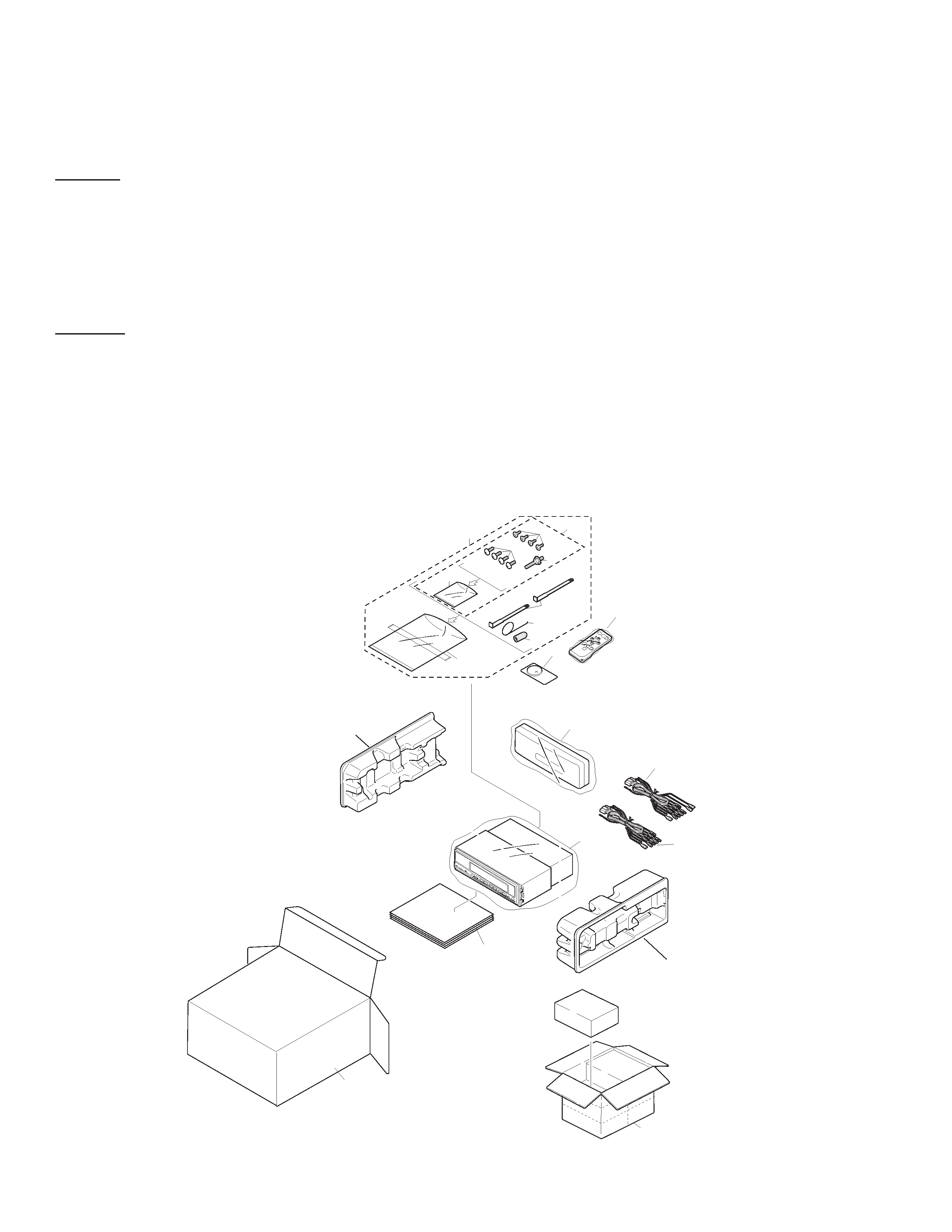
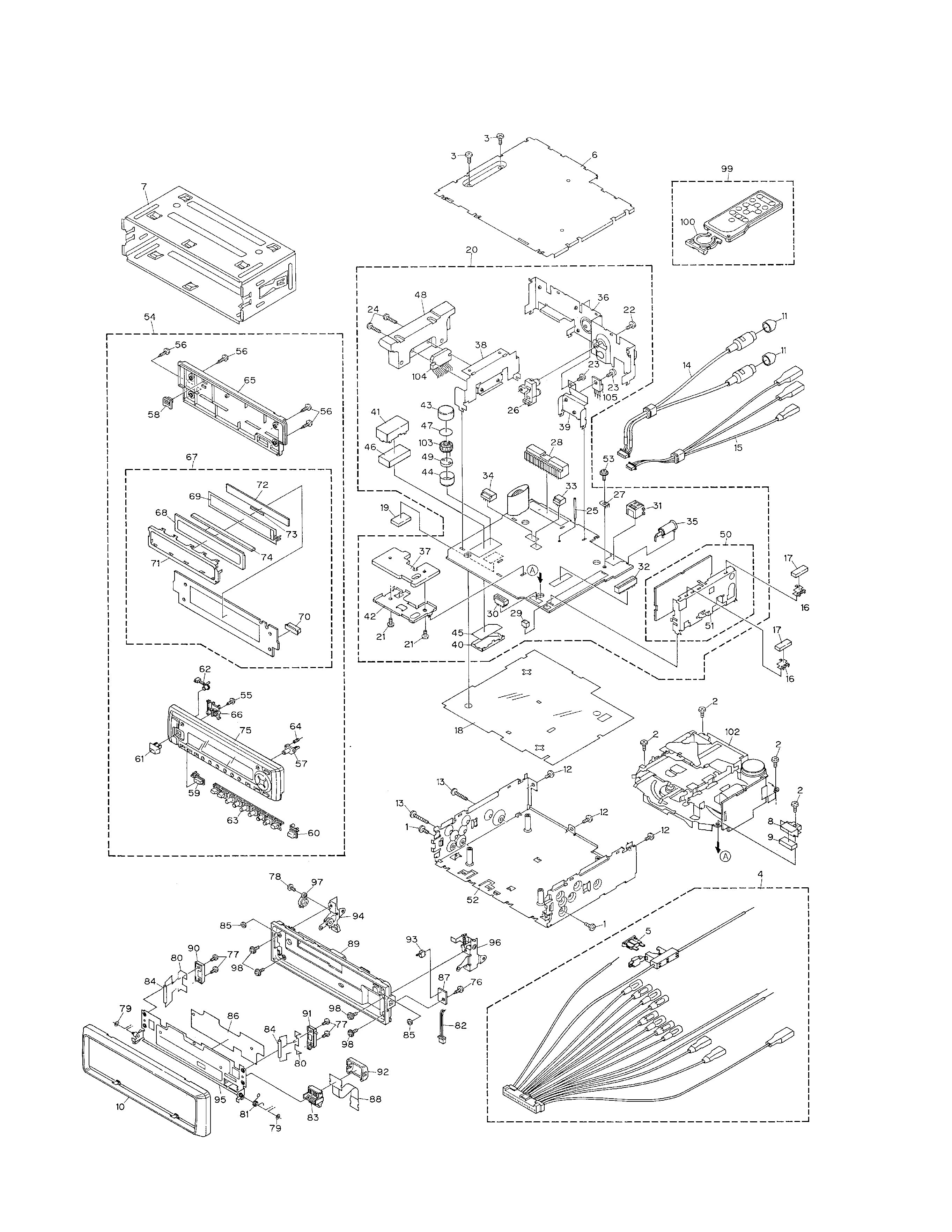
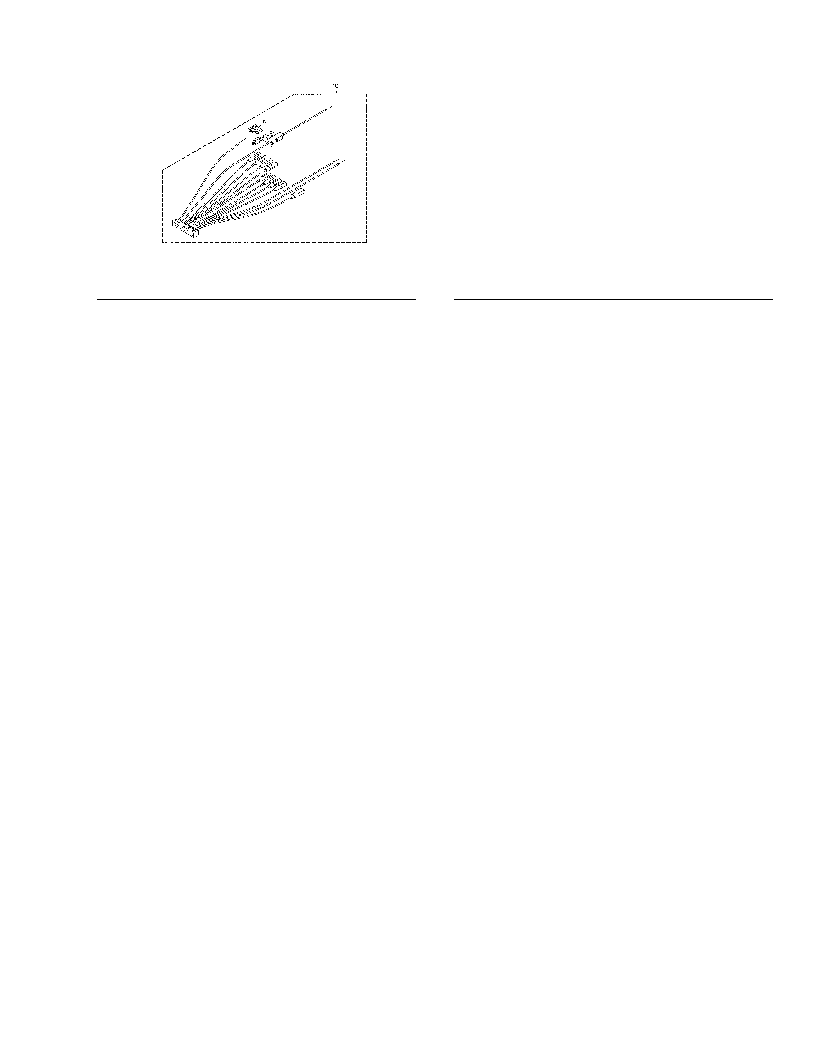
2. EXPLODED VIEWS AND PARTS LIST......................2
3. SCHEMATIC DIAGRAM ..........................................10
4. PCB CONNECTION DIAGRAM ...............................20
5. ELECTRICAL PARTS LIST .......................................30
6. ADJUSTMENT ........................................................40
7. GENERAL INFORMATION ......................................42
7.1 PARTS.................................................................42
7.1.1 IC ...............................................................42
7.1.2 DISPLAY ...................................................47
7.2 DIAGNOSIS........................................................48
7.2.1 DISASSEMBLY .........................................48
7.2.2 TEST MODE .............................................49
7.3 BLOCK DIAGRAM..............................................52
8. OPERATIONS AND SPECIFICATIONS ...................53