PIONEER HTZ-77DV/DLXJ/NC Owner's Manual

Cover page of PIONEER HTZ-77DV/DLXJ/NC Owner's Manual

Owner's Manual for PIONEER HTZ-77DV/DLXJ/NC, downloadable as a PDF file.

Manual details

  • Immediate download after payment.
  • Delivered as a PDF file.
  • The manual has 2 pages
  • File size: 1.28 MB
  • Available language versions: English, Chinese Simplified
  • Different language versions may vary sligthly in file size and page count.

We guarantee that...

  • our manuals are complete,
  • our manuals are checked with antivirus,
  • We'll issue refund if the manual is damaged, incomplete or unreadable (our refund policy)

Sample pages

Thumbnail of page 1Thumbnail of page 2Thumbnail of page 3Thumbnail of page 4
Thumbnail of page 5Thumbnail of page 6
background image
Setting Up the
System
Although compact, this system delivers powerful Dolby Digital and DTS
sound to turn your room into a home theater. The appearance of the
system is designed to match modern interiors. If you are using the
system for the first time, these two pages show you how to connect the
system and set up the speakers.
Check supplied accessories
Confirm that the following accessories are in the box when you open it.
Remote control unit
Dry cell batteries
(size AA/R6P) x 2
Display unit (AXX7107)
AM loop antenna
FM antenna
Control cable A
Control cable B
Display cable
Video cord
Gray /
Yellow plugs
Blue plugs /
Power cord
Speaker cords /
5 m x 3 (for center, front L-R speakers)
Printed in
<ARE7295-A>
Operating instructions
1 Connect the subwoofer unit and DVD tuner system with 2 cables
1. Plug the control cable A (blue
plugs) into the A jack (USE ONLY
WITH S-DV77SW) on the rear of
the DVD tuner system.
2. Plug the other end of the control
cable A into the A jack (TO
MODEL XV-DV77) on the rear of
the powered subwoofer unit.
3.
In the same way, plug one end of
the control cable B (black plugs)
into the B jack (USE ONLY WITH
S-DV77) on the rear of the DVD
tuner system, and the other end
into the B jack (TO MODEL XV-
DV77) on the powered
subwoofer unit.
2 Connect the DVD tuner system and display unit
1. Plug the L-shaped end of the
display cable into the connector
on the rear of the display unit
(AXX7107).
2. Plug the other end of the display
cable into USE ONLY WITH
AXX7107 jack on the DVD tuner
system.
3 Setup the AM loop antenna
1. Bend the stand in the direction
indicated by the arrow.
2. Clip the loop onto the stand.
3. If you want to fix to a wall or
other surface, perform step 2
after first securing the stand with
screws.
4 Connect the AM and FM antennas
1. Twist off the plastic insulation on
the end of each strand of the AM
antenna.
2. Press the AM antenna terminal
lever to open it, and insert a wire.
Release the lever to secure.
3. Connect the other strand of the
AM antenna in the same way.
4. Press the FM antenna terminal
lever to open it, and insert a wire.
Release the lever to secure.
Note
· Keep antenna cables away from other cables
and the display unit and main set.
· To assure optimum reception, pull the FM
antenna so that it is fully extended and not
coiled or hanging at the rear of the unit.
· If reception with the supplied antenna is poor,
see page 83 of the main operating instructions
for details on the Connecting Outdoor
Antennas.
Non-skid pads x 19 (satellite speakers)
10 m x 2 (for rear L-R speakers)
COAX
IN
OPT
.IN
OPT
.OUT
EL
R CT-L1
1
USE ON
LY
WITH AAX
7107
O
1
SYSTEM
AUD
IO IN
A
R
L
VIDEO
2
VIDEO
3
USE
ONL
Y WITH
S-DV77
SW OR
S-DV88SW
S-VIDEO
OUT
VIDE
O
OUT
USE
ONL
Y WITH
S-D
V77SW
OR
S-D
V88SW
B
Black plugs /
<TSWZW/01G00001>
COAX IN
OPT.IN
OPT.O
UT
AM LO
OP
ANTEN
NA
FM
UNBAL
75
EL
R CT-L11
USE ONL
Y
WITH
AAX7107
VIDEO
1
SYSTEM
AUDIO
IN
NTEN
NA
A
R
L
H
VIDEO
2
VIDEO
3
USE O
NLY W
ITH
S-DV77
SW OR
S-DV88
SW
S-VIDE
O
OUT
VIDEO
OUT
USE O
NLY W
ITH
S-DV7
7SW
OR
S-DV8
8SW
B
COAX
IN
OPT
.IN
O
AM LOOP
ANTENNA
FM
UNB
AL
75
FROM
MODEL
PDR
-L77
OR CT-L11
OR
MJ-L1
VIDEO
1
SYSTEM
AUDIO
IN
ANTEN
NA
R
L
H
H
VIDEO
2
VIDEO
3
S-VID
EO
OUT
VIDE
O
OUT
Connecting
Caution
When connecting this system or changing connections, be
sure to switch power OFF with the STANDBY/ON button, and
disconnect the power cord from the wall socket.
After completing all connections, connect the power cord to
the wall socket.
Memo
· The display unit (AXX7107) features holes on the rear to enable
hanging on a wall, so you can install it wherever you like.
÷
Non-slip pads
· Remove the supplied non-slip pads from the paper, and stick
three onto the base of each satellite speaker.
STANDBY/ON
÷
1.
A
2.
A
3.
B
B
1.
2.
1.
2.
3.
1.
2.
3.
4.
÷
÷
÷
COAX I
N
OPT.IN
OPT.O
UT
OOP
NNA
FM
UNB
AL
75
1
USE
ONLY
WITH AAX7107
VIDEO
1
SYSTEM
AUDIO
IN
NNA
A
R
L
H
VIDEO
2
VIDEO
3
USE
ONLY
WITH
S-DV77SW
OR
S-DV88
SW
S-VID
EO
OUT
VIDEO
OUT
USE O
NLY W
ITH
S-DV7
7SW O
R
S-DV8
8SW
B
COAX IN
OPT.IN
O
AM LOOP
ANTENNA
FM
UNBAL
75
VIDEO
1
AUDIO
IN
ANTENNA
R
L
H
VIDEO
2
VIDEO
3
S-VIDE
O
OUT
VIDEO
OUT
H
<CENTER> under side
<FRONT, REAR> under side
Non-skid pads x 4 (subwoofer)
Fix to the underside of the subwoofer
OPT
.IN
OPT.OUT
AM LOOP
ANTENNA
FM
UNB
AL
75
FROMM
ODEL
PDR-L77
OR CT
-L11
OR
MJ-L1
USE ONL
Y
WITH
AAX7107
VIDEO
1
SYSTEM
AUDIO
IN
ANTENNA
A
R
L
H
H
VIDEO
2
VIDEO
3
USE
ONLY
WITH
S-DV77SW
OR
S-DV88SW
S-VIDEO
OUT
VIDEO
OUT
USE
ONLY
WITH
S-D
V77SW
OR
S-DV88S
W
B
SURR
OUND
(REAR)
77
1
A
A
1
1
2
3
4
4
B
B
Published by Pioneer Corporation.
Copyright © 2001 Pioneer Corporation.
All rights reserved.
©
background image
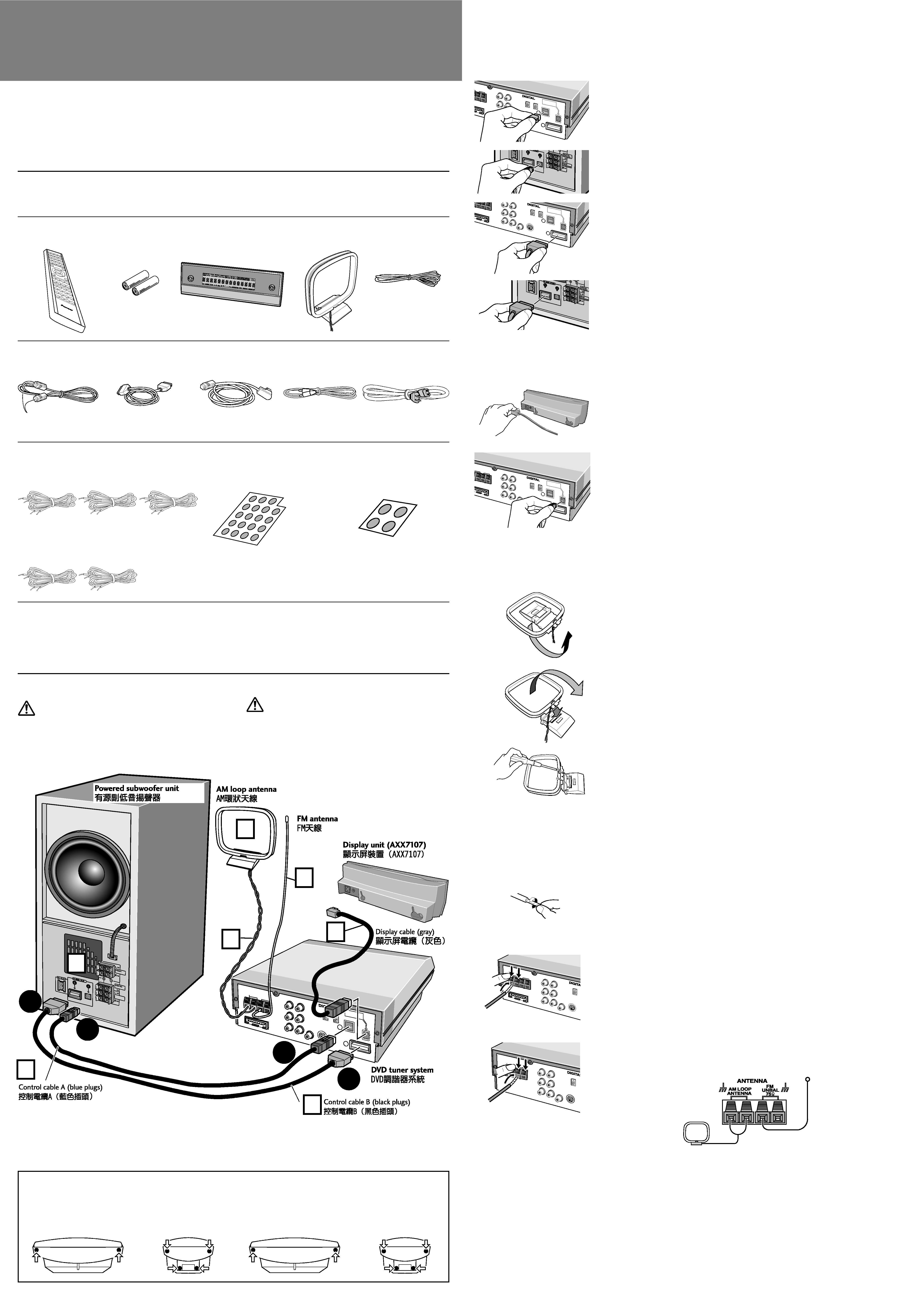
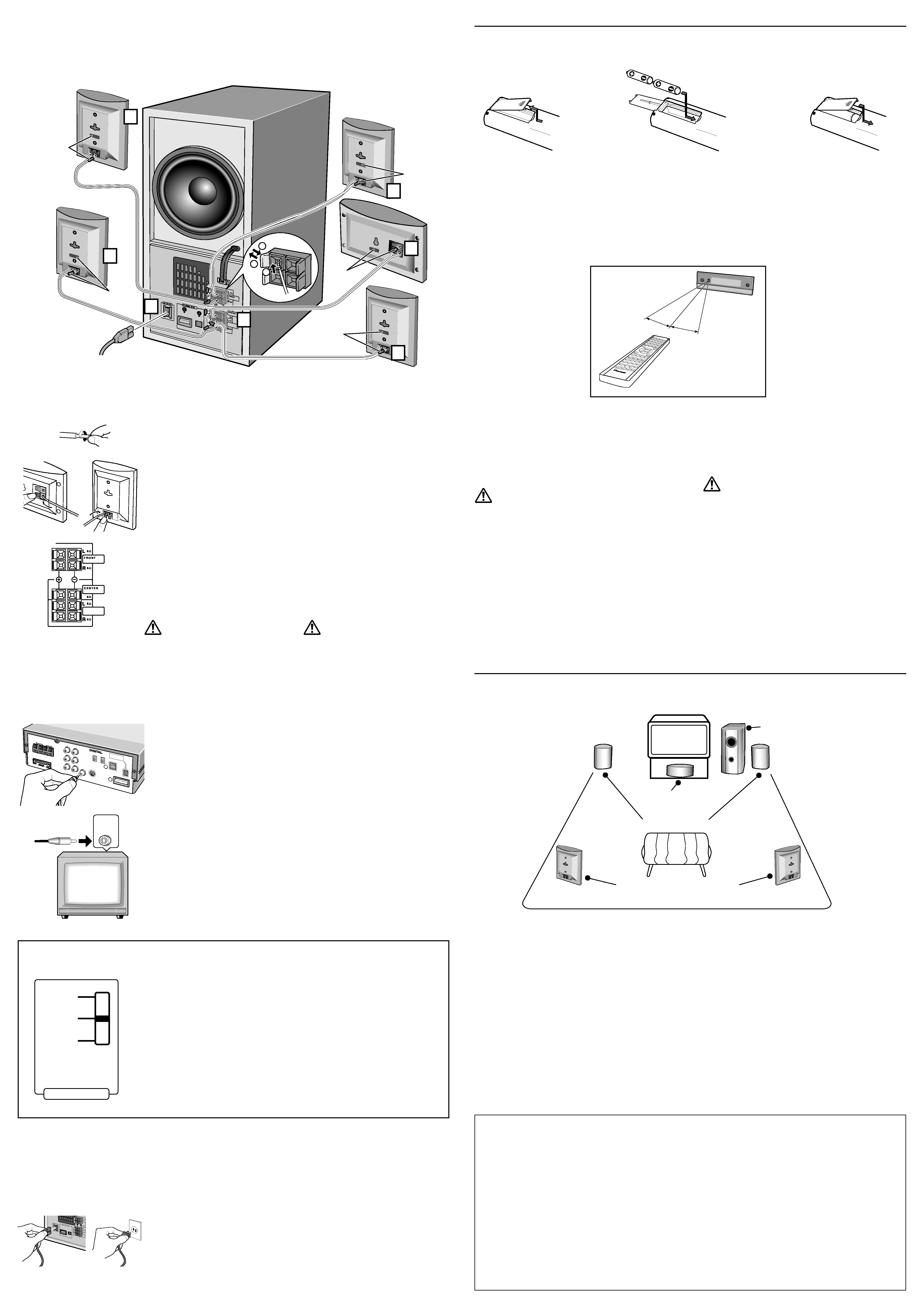
5 Connect the speakers
1. Twist and pull off the insulation
at both ends of the speaker cord.
2. Each speaker cord, speaker and
terminal on the main unit has a
colored marker. Match up the
terminal with the right speaker
cord and speaker. Insert the wire
while pressing the speaker
terminal tab. Insert the wire with
the colored marker into the red
side, and the other wire into the
black side.
[Satellite speakers] Release the lever.
[Powered subwoofer] Pull back the lever.
3. Repeat for all speakers and the
subwoofer unit.
Caution:
Do not use the speakers with an amp other than
this system's as it may result in damage or fire.
Note
It makes connecting the speaker cords easier if you first stick the
supplied cord labels on either end of each cord.
SURROUND
(REAR)
6 Connect the TV
1. Connect the supplied video cord
(yellow plugs) to the DVD tuner
system's VIDEO OUT jack.
2. Connect the other end of the
video cord to the TV's VIDEO IN
jack.
Note
You can also use an S-Video cord (not
supplied) to connect the S-Video jack of this
unit to an S-Video input on your TV.
VIDEO
IN
7 Connect the power cord
1. Connect the power cord to the
powered subwoofer unit's AC
INLET.
2. Connect the power cord to a wall
socket.
Loading batteries in the remote
control
Incorrect use of batteries may cause leakage or rupture.
Always be sure to follow these guidelines:
· Always insert batteries into the battery compartment correctly
matching the positive
ª and negative · polarities, as shown
by the display inside the compartment.
· Never mix new and used batteries.
· Batteries of the same size may have different voltages, depending
on brand. Do not mix different brands of batteries.
· When disposing of used batteries,
please comply with governmental
regulations or environmental
public instruction's rules that
apply in your country or area.
The remote control can be used
within a range of about 7 meters from
the remote sensor of the display unit,
and within a 30 degree angle.
Note
· In order to prevent battery
leakage, remove the batteries
when not using the remote control
for an extended period (one
month or more). If leakage occurs, carefully wipe away any
battery fluid inside the compartment, and replace the batteries with
new ones.
· Do not allow books or other objects to rest on top of the remote
control, since the buttons may be depressed, causing faster
exhaustion of the batteries.
Precautions:
· The remote control may not work if there is an obstacle between
the remote control and the display unit, or if the remote control is
not directed towards the remote sensor of the display unit at the
correct angle.
· The remote control may not work properly if strong light such as
direct sunlight or fluorescent light is shining onto the display
unit's remote sensor.
· The remote control may not work properly when this unit is used
near devices emitting infrared rays, or when remote controls of
other devices which use infrared rays are used.
On the other hand, the use of this remote control may cause other
devices to work improperly.
· When the operating range of this remote control becomes too
short, replace the batteries.
Speakers placement
Place speakers as shown below to achieve the optimum
surround sound effect.
Note
· Install the main front left and right speakers at an equal distance
from the TV.
· For optimum effect, install the rear speakers slightly above ear
level.
· This system's speakers are magnetically shielded (EIAJ), so there's
virtually no picture color distortion when they are placed near a
TV. In the rare event that there is some picture color interference,
switch power to the TV off, and wait 15 to 30 minutes before
switching on again.
· Install the center speaker above or below the TV so that the sound
of the center channel is localized at the TV screen.
· When installing the center speaker on top of the TV, be sure to
secure it with tape or some other suitable means. Otherwise, the
speaker may fall from the TV due to external shocks such as
earthquakes, endangering those nearby or damaging the speaker.
COAX
IN
OPT.IN
OPT.O
UT
AM LO
OP
ANTEN
NA
FM
UNBAL
75
FROMM
ODEL
PDR-L
77 OR C
T-L11
OR
MJ-L1
USE ONL
Y
WITH
AAX7107
VIDEO
1
SYSTEM
AUDIO
IN
ANTEN
NA
A
R
L
H
H
VIDEO
2
VIDEO
3
USE O
NLY W
ITH
S-DV77
SW OR
S-DV88
SW
S-VIDE
O
OUT
VIDEO
OUT
USE O
NLY W
ITH
S-DV7
7SW O
R
S-DV8
8SW
B
SURR
OUND
(REAR)
77
1
2
3
5
5
5
5
5
5
7
Front L
Front R
Surround (Rear L)
Surround (Rear R)
Red
Grey
Blue
Green
Center
10m
5m
5m
5m
White
1.
2.
3.
1.
VIDEO OUT
2.
VIDEO IN
1.
AC
INLET
2.
·
ª
·
·
·
·
·
·
·
·
·
·
·
·
·
·
·
7m
30°
30°
Switching the demo mode on/off
This system features a demonstration display. When the demo
mode is on, the demo display automatically starts after the system
is plugged in, or if it's inactive for more than five minutes in the
DVD/CD function.
1
Switch the system into standby.
2
Press SYSTEM MENU and select DEMO
MODE.
Change menu options using the
2 and 3 buttons. Press
ENTER
to select the currently displayed option.
3Use the
5 or button to select DEMO ON
or DEMO OFF as required. Press ENTER.
The system returns to standby.
1
2
SYSTEM MENU
DEMO MODE
2 3
ENTER
3
5
DEMO ON
DEMO OFF
ENTER
Dry cell batteries (size AA/
R6P) x 2
Center speaker
Front speakers
Surround speakers (Rear )
Subwoofer
Line Voltage Selector Switch
( Multi voltage model only)
There is a Voltage Selector. Be sure this is set
correctly.
Always check that this selector is set
properly before plugging the power cord
into the wall outlet.
1. Disconnect the power cord.
2. Use a small-sized screwdriver (flat
blade).
3. Insert the screwdriver into the
groove on the voltage selector,
and adjust the voltage selector.
1.
2.
3.
VOLTAGE SELECTOR
110 V
-120 V
220 V
-230 V
240 V

Reviews

There are no reviews of this manual yet.