1
HTP102-SW
Service
Manual
ORDER NO.
PET98005
PIONEER ELECTRONIC CORPORATION 4-1, Meguro 1-Chome, Meguro-ku, Tokyo 153-8654, Japan
PIONEER ELECTRONICS SERVICE, INC. P.O. Box 1760, Long Beach, CA 90801-1760, U.S.A.
PIONEER ELECTRONIC (EUROPE) N.V. Haven 1087, Keetberglaan 1 B-9120 Melsele, Belgium
PIONEER ELECTRONICS ASIACENTRE PTE. LTD. 501 Orchard Road, #10-00, Wheelock Place, Singapore 238880
©PIONEER ELECTRONIC CORPORATION 1998
1998 Printed in U.S.A.
· Place unit upside-down on a soft cloth so as not to scratch the
top panel.
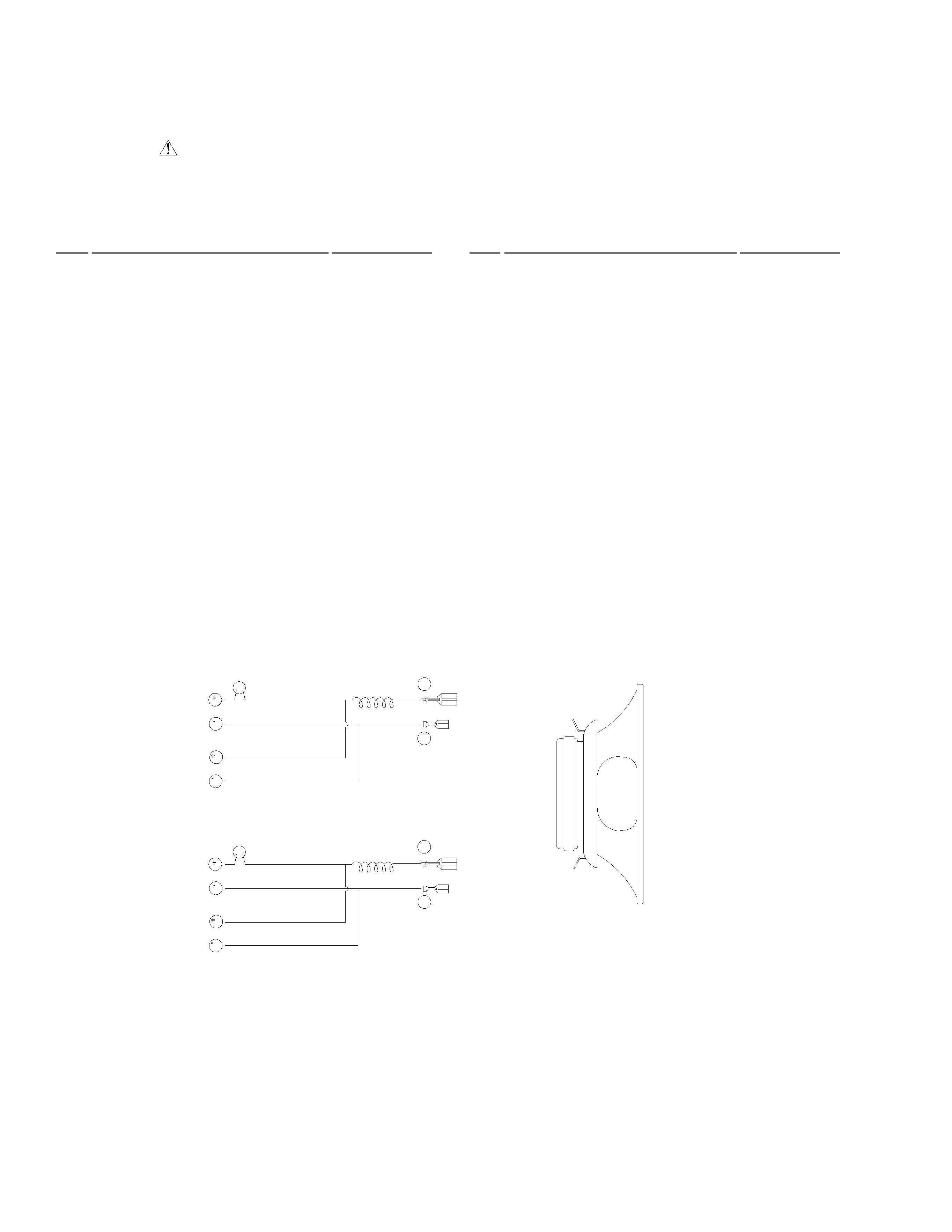
· The woofer is attached to the baffle by 4 screws. To detach the
woofer, unfasten those screws and lift up. Detach the speaker
wires by gently pulling the connectors off the speakers' binding
posts. When attaching the woofer, push the connectors on to
the binding posts and attach the speaker to the baffle by
tightening the screws.
· Once the woofer has been removed, the terminal cup may be
removed by unfastening the six screws that fasten it to the
backboard. Note: Do not pull on wires at the terminal side if
not disconnected from the woofer as this may result in damage
to the binding posts, wires, or connectors. To attach, re-fasten
the screws on to the backboard making certain that the text on
the terminal cup is oriented in the correct direction.
· The cosmetic duct is attached to the cabinet by application of
adhesives. To detach, first remove woofer as described above.
From within the cabinet, rock the port tube back and forth until
the assembly comes loose. To attach, press-fit the inside and
outside port rings on to the port tube and apply hot melt
adhesive around the circumference of outside port ring and
press fit on to the front board.
· The foot may be detached by removing one external screw. To
attach, refasten foot with screw.
HOW TO REASSEMBLE AND
DISASSEMBLE
65S
This service manual is intended for qualified service technicians; it is not
meant for the casual do-it- your selfer. Qualified technicians have the
necessary test equipment and tools, and have been trained to properly and
safely repair complex products such as those covered by this manual.
Improperly performed repairs can adversely affect the safety and reliability
of the product and may void the warranty. If you are not qualified to
perform the repair of this product properly and safely, you should not risk
trying to do so and refer the repair to a qualified service technician.
WARNING
THIS PRODUCT CONTAINS LEAD IN SOLDER AND CERTAIN
ELECTRICAL PARTS CONTAIN CHEMICALS WHICH ARE
KNOWN TO THE STATE OF CALIFORNIA TO CAUSE CANCER,
BIRTH DEFECTS OR OTHER REPRODUCTIVE HARM.
Health & Safety Code Section 25249.6 - Proposition 65
SPEAKER SYSTEM
HTP102-SW