PIONEER ELECTRONIC CORPORATION
4-1, Meguro 1-Chome, Meguro-ku, Tokyo 153-8654, Japan
PIONEER ELECTRONICS SERVICE INC.
P.O.Box 1760, Long Beach, CA 90801-1760 U.S.A.
PIONEER ELECTRONIC [EUROPE] N.V.
Haven 1087 Keetberglaan 1, 9120 Melsele, Belgium
PIONEER ELECTRONICS ASIACENTRE PTE.LTD. 501 Orchard Road, #10-00, Wheelock Place, Singapore 238880
C PIONEER ELECTRONIC CORPORATION 1998
K-ZED. FEB.1998 Printed in Japan
ORDER NO.
CRT2190
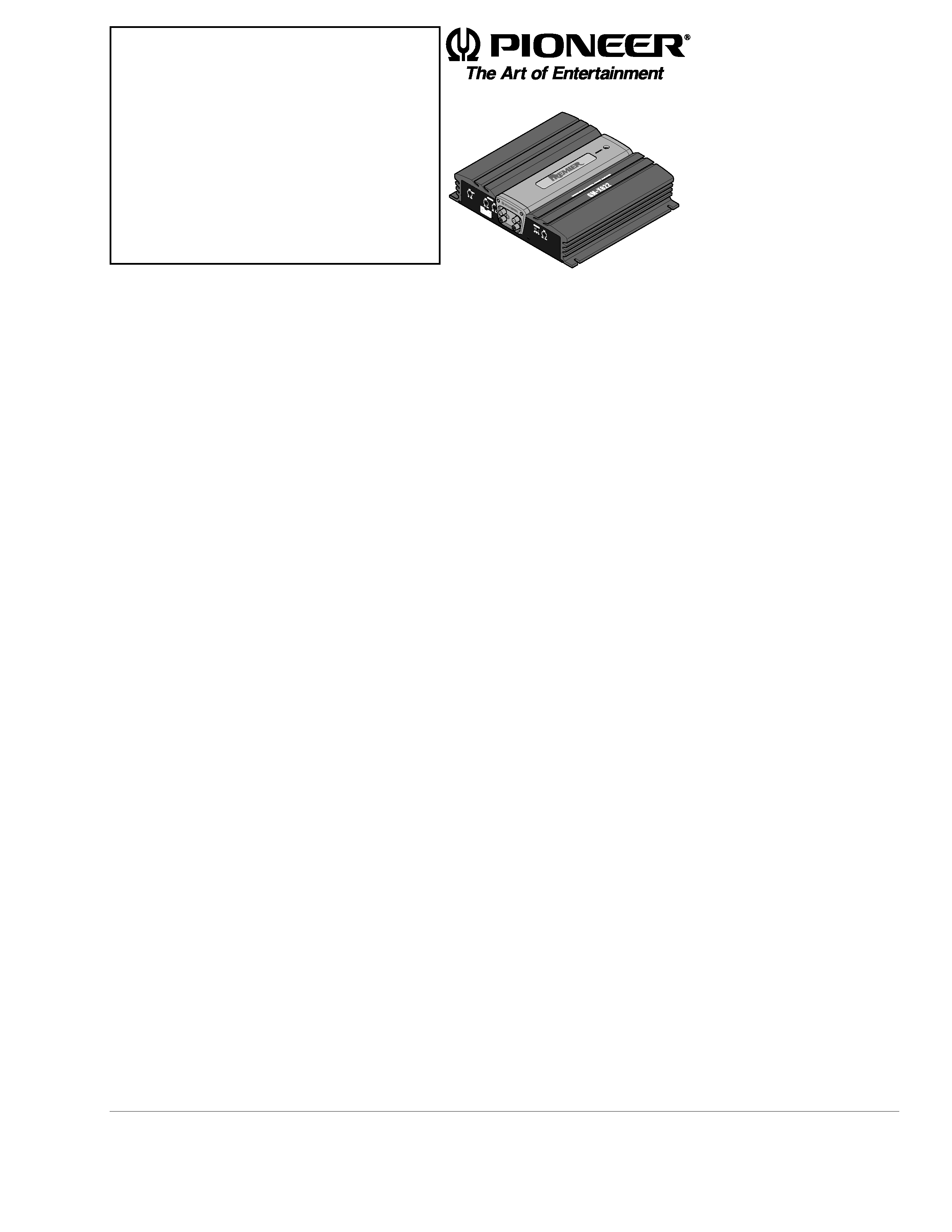
BRIDGEABLE POWER AMPLIFIER
Service
Manual
GM-X622
X1R/UC
GM-X622/X1R/UC
CONTENTS
1. SAFETY INFORMATION ............................................2
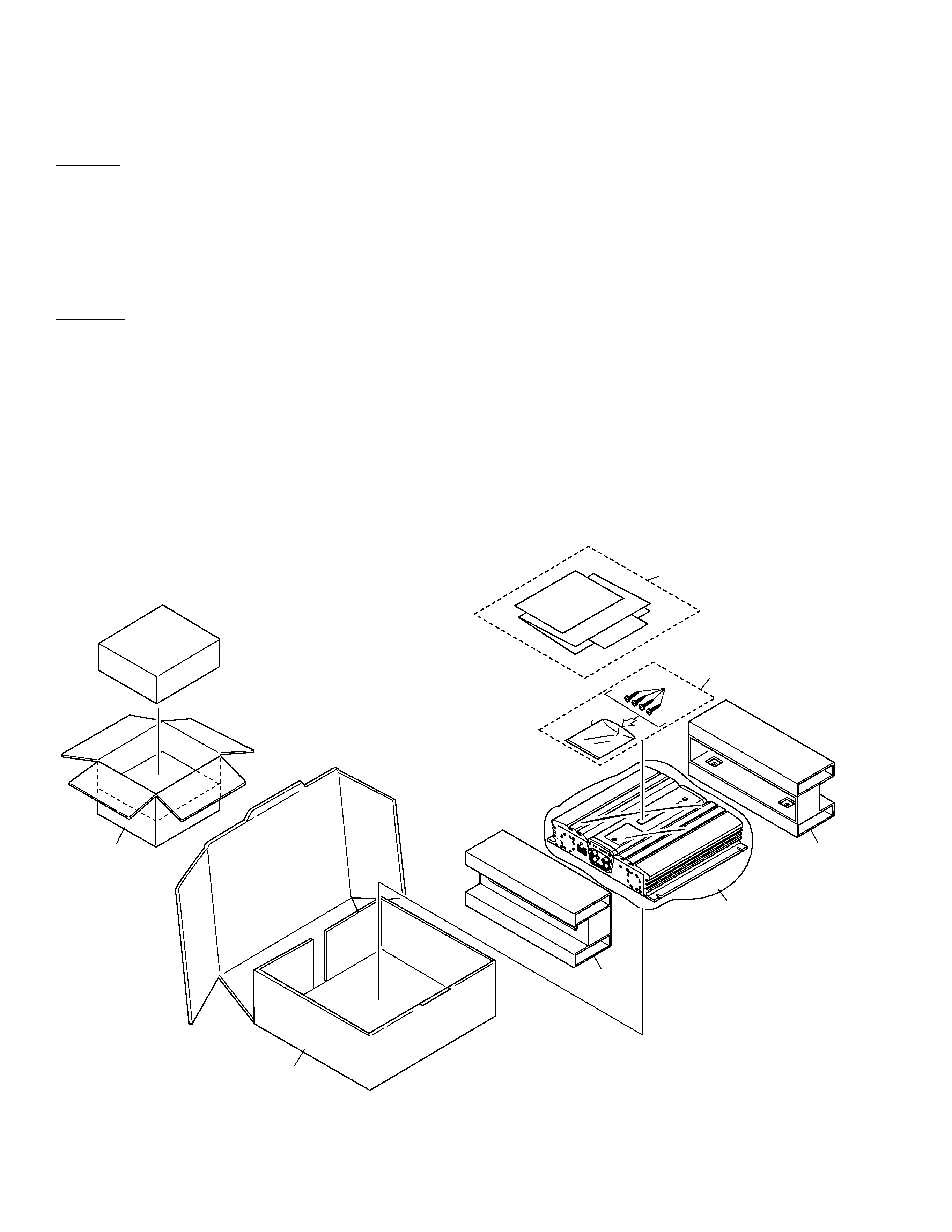
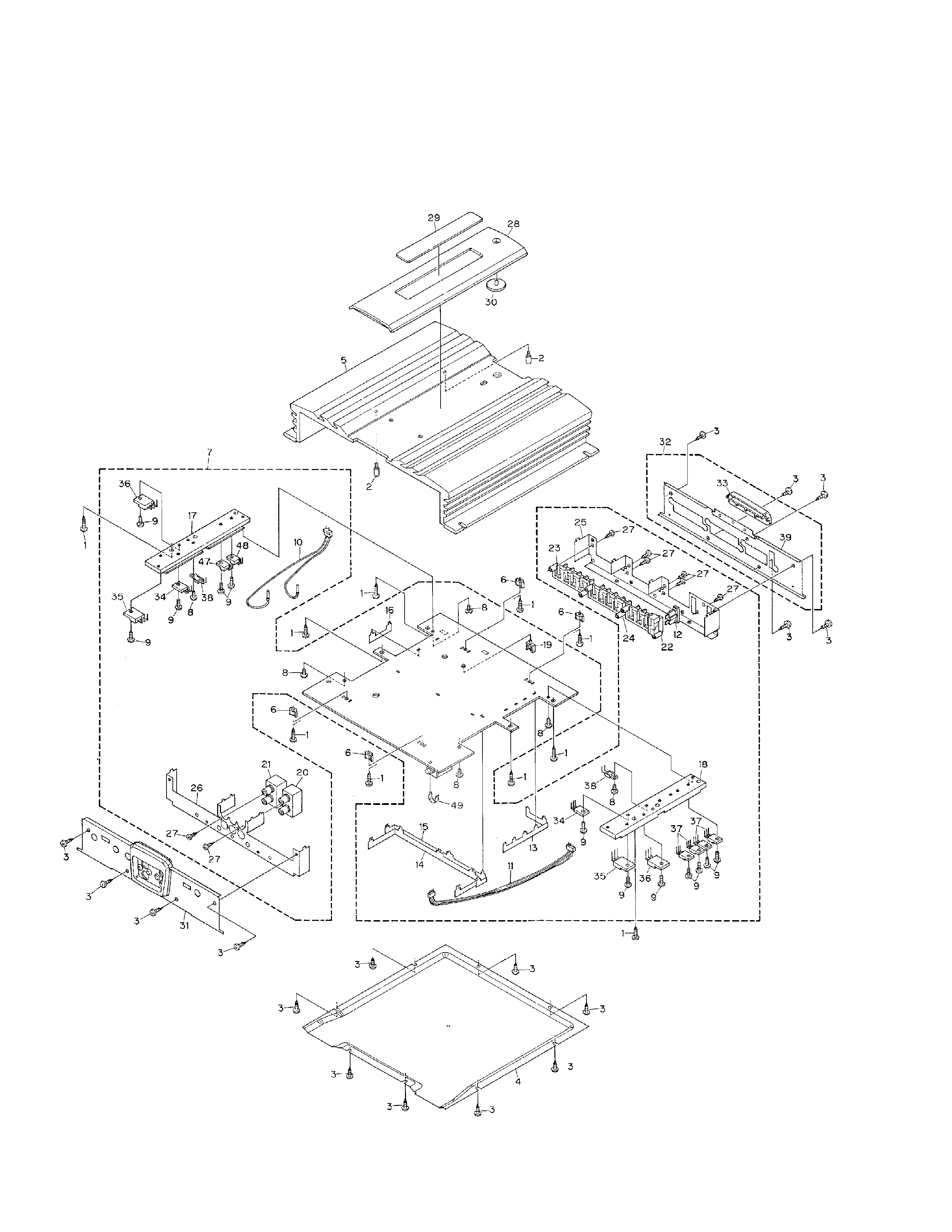
2. EXPLODED VIEWS AND PARTS LIST .......................2
3. SCHEMATIC DIAGRAM .............................................6
4. PCB CONNECTION DIAGRAM ................................12
5. ELECTRICAL PARTS LIST ........................................14
6. ADJUSTMENT..........................................................17
7. GENERAL INFORMATION .......................................18
7.1 IC .........................................................................18
7.2 DISASSEMBLY ...................................................19
7.3 BLOCK DIAGRAM ..............................................20
8. OPERATIONS AND SPECIFICATIONS.....................21
GM-X622
X1R/EW
GM-X622
X1R/ES
GM-X522
X1R/UC