PIONEER GM-8337ZT-91/X1H/E Service Manual

Cover page of PIONEER GM-8337ZT-91/X1H/E Service Manual

Service Manual for PIONEER GM-8337ZT-91/X1H/E, downloadable as a PDF file.

Manual details

  • Immediate download after payment.
  • Delivered as a PDF file.
  • The manual has 44 pages
  • File size: 2.5 MB
  • Available language versions: English
  • Different language versions may vary sligthly in file size and page count.

We guarantee that...

  • our manuals are complete,
  • the manual includes circuit diagrams,
  • our manuals are checked with antivirus,
  • We'll issue refund if the manual is damaged, incomplete or unreadable (our refund policy)

Sample pages

Thumbnail of page 1Thumbnail of page 2Thumbnail of page 3Thumbnail of page 4
Thumbnail of page 5Thumbnail of page 6Thumbnail of page 7Thumbnail of page 8
Thumbnail of page 9
background image
ORDER NO.
CRT3014
PUB. NO.
CRT3014
AUDIO SYSTEM
POWER AMPLIFIER
Manufactured for TOYOTA
by PIONEER CORPORATION
VEHICLE
DESTINATION
PRODUCED AFTER
TOYOTA PART No.
ID No.
PIONEER MODEL No.
LEXUS RX330 Europe, Middle Near East,
February 2003
86100-48010
GM-8337ZT/E
Australia, General Area
86280-48070
GM-8337ZT-91/E
86100-48010
GM-8337ZT-92/E
RX330
Service
Manual
background image
2
1
234
12
34
F
E
D
C
B
A
GM-8337ZT/E
For details, refer to "Important symbols for good services".
SAFETY INFORMATION
This service manual is intended for qualified service technicians; it is not meant for the casual do-it-yourselfer.
Qualified technicians have the necessary test equipment and tools, and have been trained to properly and safely repair
complex products such as those covered by this manual.
Improperly performed repairs can adversely affect the safety and reliability of the product and may void the warranty.
If you are not qualified to perform the repair of this product properly and safely, you should not risk trying to do so
and refer the repair to a qualified service technician.
NOTE:
- When diagnosing a product, take care of its heated portion.
Power IC
(IC802,803)
Power Supply IC (IC901,902)
DSP IC
(IC201)
Heat Sink
IC Holder
GM-8337ZT/E
- Supplementally model is identical to the original except for the addition of following items.
*: Non Spare Part
Part No.
Description
GM-8337ZT-91/E
GM-8337ZT-92/E
Cover
CEG1045(x2)
CEG1045(x3)
Polyethylene Bag
CEG1185
CEG1185
* Polyethylene Bag
Not used
CEG1185
Carton
CHG5005
CHG4865
Contain Box
CHL5095(x1/4)
CHL5085(x1/4)
background image
3
5
6
7
8
F
E
D
C
B
A
5
6
7
8
GM-8337ZT/E
[ Important symbols for good services ]
In this manual, the symbols shown-below indicate that adjustments, settings or cleaning should be made securely.
When you find the procedures bearing any of the symbols, be sure to fulfill them:
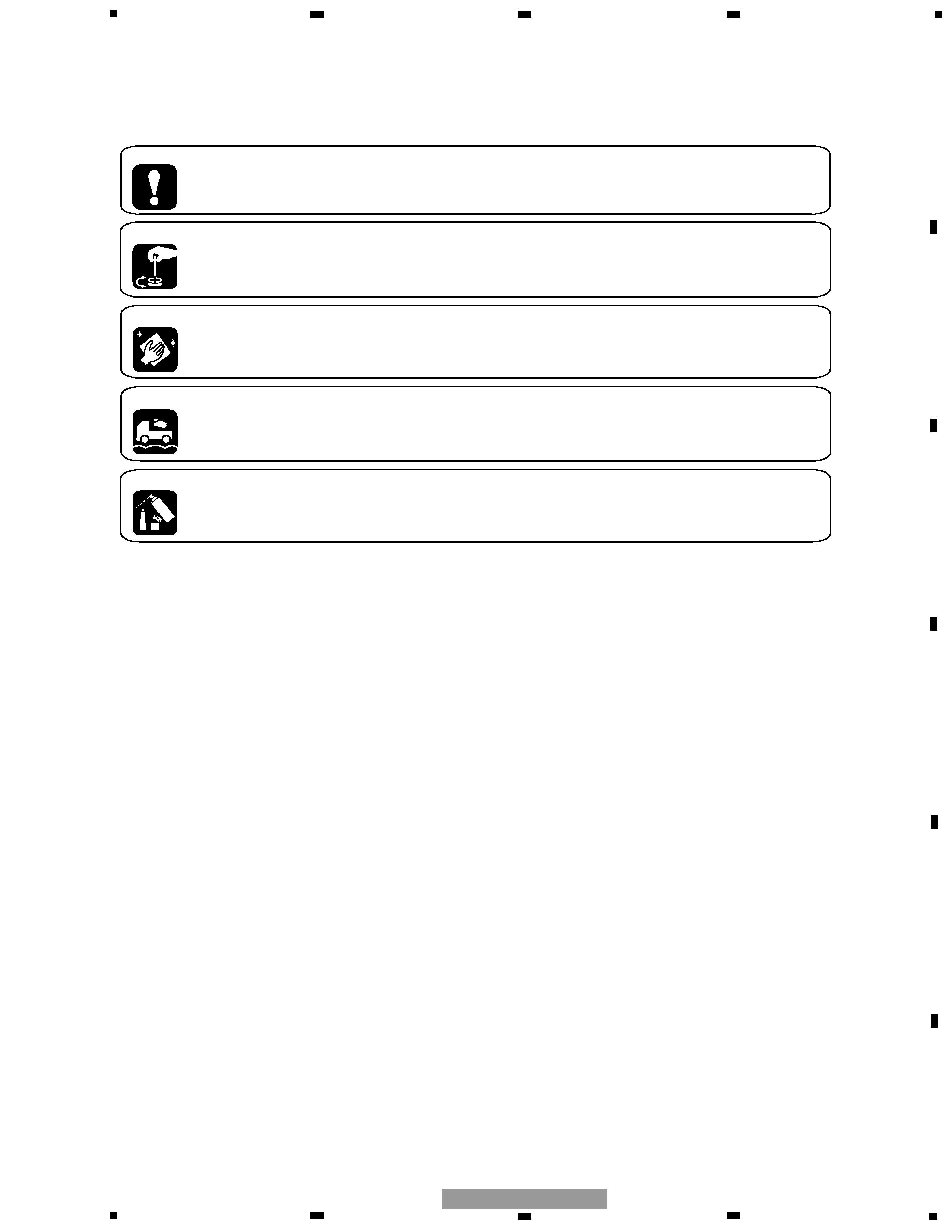
2. Adjustments
To keep the original performances of the product, optimum adjustments or specification confirmation is indispensable.
In accordance with the procedures or instructions described in this manual, adjustments should be performed.
3. Cleaning
For optical pickups, tape-deck heads, lenses and mirrors used in projection monitors, and other parts requiring cleaning,
proper cleaning should be performed to restore their performances.
5. Lubricants, glues, and replacement parts
Appropriately applying grease or glue can maintain the product performances. But improper lubrication or applying
glue may lead to failures or troubles in the product. By following the instructions in this manual, be sure to apply the
prescribed grease or glue to proper portions by the appropriate amount.For replacement parts or tools, the prescribed
ones should be used.
4. Shipping mode and shipping screws
To protect the product from damages or failures that may be caused during transit, the shipping mode should be set or
the shipping screws should be installed before shipping out in accordance with this manual, if necessary.
1. Product safety
You should conform to the regulations governing the product (safety, radio and noise, and other regulations), and
should keep the safety during servicing by following the safety instructions described in this manual.
CONTENTS
SAFETY INFORMATION............................................2
1. SPECIFICATIONS .......................................................3
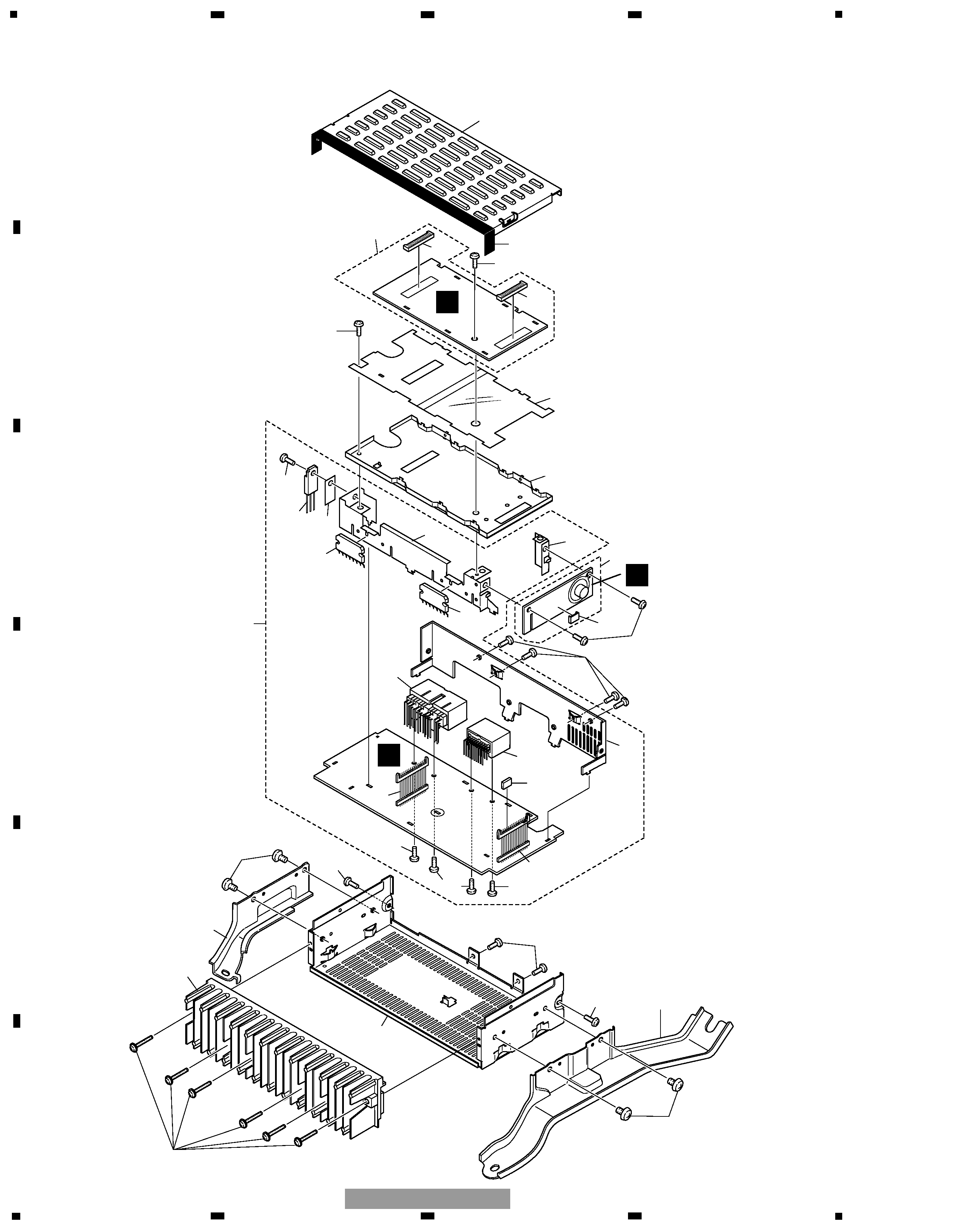
2. EXPLODED VIEWS AND PARTS LIST ......................4
2.1 EXTERIOR ............................................................4
3. BLOCK DIAGRAM AND SCHEMATIC DIAGRAM ....6
3.1 BLOCK DIAGRAM ...............................................6
3.2 SCHEMATIC DIAGRAM(GUIDE PAGE) ..............8
4. PCB CONNECTION DIAGRAM................................14
4.1 DSP UNIT...........................................................14
4.2 AMP UNIT..........................................................18
4.3 ASL UNIT ...........................................................22
5. ELECTRICAL PARTS LIST........................................23
6. ADJUSTMENT .........................................................28
7. GENERAL INFORMATION.......................................31
7.1 DIAGNOSIS .......................................................31
7.1.1 DISASSEMBLY .........................................31
7.1.2 CONNECTOR FUNCTION DESCRIPTION ......34
7.2 IC ........................................................................35
7.3 EXPLANATION...................................................39
7.3.1 SYSTEM BLOCK DIAGRAM .....................39
7.3.2 OPERATIONAL FLOW CHART .................42
8. OPERATIONS ...........................................................43
1. SPECIFICATIONS
Power source . . . . . . . . . . . . .13.2±0.1V(10.5-16.0V)
Grounding . . . . . . . . . . . . . . . .Negative type
Backup current . . . . . . . . . . . .0.3mA or less
Dimensions(No Bracket) . . . .210mm(W)x51mm(H)x128mm(D)
Weight . . . . . . . . . . . . . . . . . . .1,415g
Maximum output power . . . .39W or more(Front-Woofer)
20W or more(Front-Squawker)
20W or more(Rear)
background image
1
11
3
4
3
2
2
3
8
7
18
19
17
3
22
14
16
15
29
13
31
30
32
21
3
3
26
25
24
10
9
6
5
20
27
12
23
28
14
14
A
B
C
4
1
234
12
34
F
E
D
C
B
A
GM-8337ZT/E
2. EXPLODED VIEWS AND PARTS LIST
2.2 EXTERIOR
background image
5
5
6
7
8
F
E
D
C
B
A
5
6
7
8
GM-8337ZT/E
1 Screw
AMZ30P220FTC
2 Screw (GM-8337ZT/E, -92) BMZ40P060FTC
3 Screw
BSZ26P060FTC
4 Chassis
CNA2538
5 Case
CNB2776
6 Shield Case
CNC9891
7 Bracket (GM-8337ZT/E, -92) CND1244
8 Bracket (GM-8337ZT/E, -92) CND1245
9 Insulator
CNM7683
10 Seal
CNM8060
11 Heat Sink
CNR1651
12 Amp Unit
CWM8303
13 Screw
BSZ26P060FTC
14 Screw(M3x6)
CBA1393
15 Connector(CN901)
CKM1363
16 Connector(CN902)
CKM1364
17 Plug(CN905)
CKS4569
18 Plug(CN906)
CKS4569
19 Connector(CN404)
CKS4639
20 Holder
CNC9893
21 Holder
CNC9894
22 Bracket
CND1109
23 Sheet
CNM7015
24 DSP Unit
CWM8304
25 Socket(CN101)
CKS4616
26 Socket(CN102)
CKS4616
27 ASL Unit
CWM8305
28 Connector(CN403)
CKS4605
29 Screw
IMS26P060FTC
30 IC(IC802)
PAL006A
31 IC(IC803)
TDA7384
32 IC(IC902)
BA178M05T
NOTE:
- Parts marked by "*" are generally unavailable because they are not in our Master Spare Parts List.
- Screws adjacent to
mark on the product are used for disassembly.
- For the applying amount of lubricants or glue, follow the instructions in this manual.
( In the case of no amount instructions, apply as you think it appropriate.)
- EXTERIOR SECTION PARTS LIST
Mark No. Description
Part No.

Reviews

There are no reviews of this manual yet.