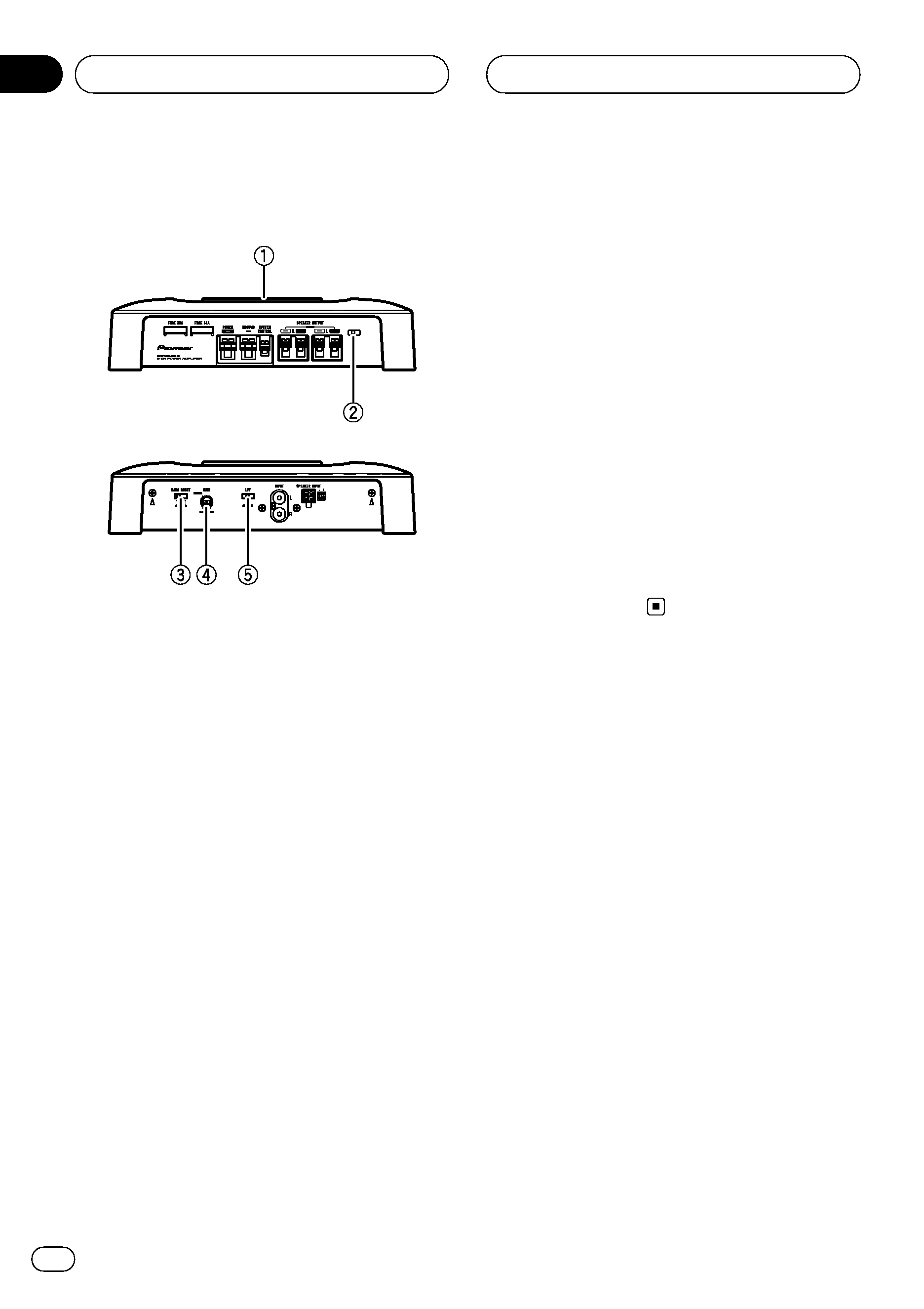
PIONEER GM-5400T/XJ/ES Owner's Manual

Cover page of PIONEER GM-5400T/XJ/ES Owner's Manual

Owner's Manual for PIONEER GM-5400T/XJ/ES, downloadable as a PDF file.

We also have service manual to this model.

Manual details

  • Immediate download after payment.
  • Delivered as a PDF file.
  • The manual has 48 pages
  • File size: 1.73 MB
  • Available language versions: Portuguese, Arabic, English, Spanish
  • Different language versions may vary sligthly in file size and page count.

We guarantee that...

  • our manuals are complete,
  • our manuals are checked with antivirus,
  • We'll issue refund if the manual is damaged, incomplete or unreadable (our refund policy)

Sample pages

Thumbnail of page 1Thumbnail of page 2Thumbnail of page 3Thumbnail of page 4
Thumbnail of page 5Thumbnail of page 6Thumbnail of page 7Thumbnail of page 8
Thumbnail of page 9
background image
Owner's Manual
Manual de instrucciones
Manual do proprietário
BRIDGEABLE TWO-CHANNEL POWER AMPLIFIER
AMPLIFICADOR DE POTENCIA DE DOS CANALES DE PUENTE
AMPLIFICADOR DE POTENCIA DE DOIS CANAIS DE PONTE
GM-5400T
English
Español
P
ortuguês
(B)
background image
Owner's Manual
Manual de instrucciones
Manual do proprietário
BRIDGEABLE TWO-CHANNEL POWER AMPLIFIER
AMPLIFICADOR DE POTENCIA DE DOS CANALES DE PUENTE
AMPLIFICADOR DE POTENCIA DE DOIS CANAIS DE PONTE
GM-5400T
English
Español
P
ortuguês
(B)
background image
Thank you for purchasing this PIONEER product.
Please read through this manual before using the product for the first time, to en-
sure proper use. After reading, please keep the manual in a safe and accessible place
for future reference.
Before you start
In case of trouble
3
Visit our website
3
Before connecting/installing the amplifier
3
Setting the Unit
What
's what 4
Setting gain properly
4
Connecting the units
Connection diagram
6
Before connecting the amplifier
6
About bridged mode
7
About suitable specification of speaker
7
Connecting the speakers
7
Connections when using the speaker input
wire
8
Connecting the power terminal
8
Connecting the speaker output terminals
9
Installation
Before installing the amplifier
11
Example of installation on the floor mat or
chassis
11
Additional information
Specifications
12
Contents
En
2
background image
In case of trouble
Should this product fail to operate properly,
contact your dealer or nearest authorized
Pioneer Service Station.
Visit our website
Visit us at the following site:
http://pioneer.jp/group/index-e.html
! We offer the latest information about
Pioneer Corporation on our website.
Before connecting/
installing the amplifier
WARNING
! The use of a special red battery and ground
wire RD-223, available separately, is recom-
mended. Connect the battery wire directly to
the car battery positive terminal
+ and the
ground wire to the car body.
! This unit is for vehicles with a 12 V battery and
negative grounding. Before installing in re-
creational vehicles, trucks or buses, check the
battery voltage.
! Always use a fuse of the rating prescribed.
The use of an improper fuse could result in
overheating and smoke, damage to the pro-
duct and injury, including burns.
! Check the connections of the power supply
and speakers if the fuse of the separately sold
battery wire or the amplifier fuse blows. Deter-
mine and resolve the cause, then replace the
fuse with identical equivalent.
! Do not allow this unit to come into contact
with liquids. Electrical shock could result.
Also, damage to this unit, smoke, and over-
heating could result from contact with liquids.
The surfaces of the amplifier and any attached
speakers may also heat up and cause minor
burns.
! In the event of any abnormality, the power
supply to the amplifier is cut off to prevent
equipment malfunction. If this occurs, switch
the system power OFF and check the power
supply and speaker connections. If you are un-
able to determine the cause, please contact
your dealer.
! Always disconnect the negative * terminal of
the battery beforehand to avoid the risk of
electric shock or short circuit during installa-
tion.
CAUTION
! Always keep the volume low enough so that
you can hear sounds from outside the vehicle.
! Extended use of the car stereo while the en-
gine is at rest or idling may exhaust the
battery.
Before you start
En
3
English
Section
01
background image
What
's what
Front side
Rear side
To adjust the switch, use a flathead screwdri-
ver if needed.
1 Power indicator
The power indicator lights up to indicate
power ON.
2 BFC (beat frequency control) switch
Located front side the unit. If beats are audi-
ble while listening to AM broadcasts via car
stereo, change the
BFC switch using a small
flathead screwdriver.
3 BASS BOOST (bass boost level control)
switch
You can select a bass boost level from 0 dB,
6 dB and 12 dB.
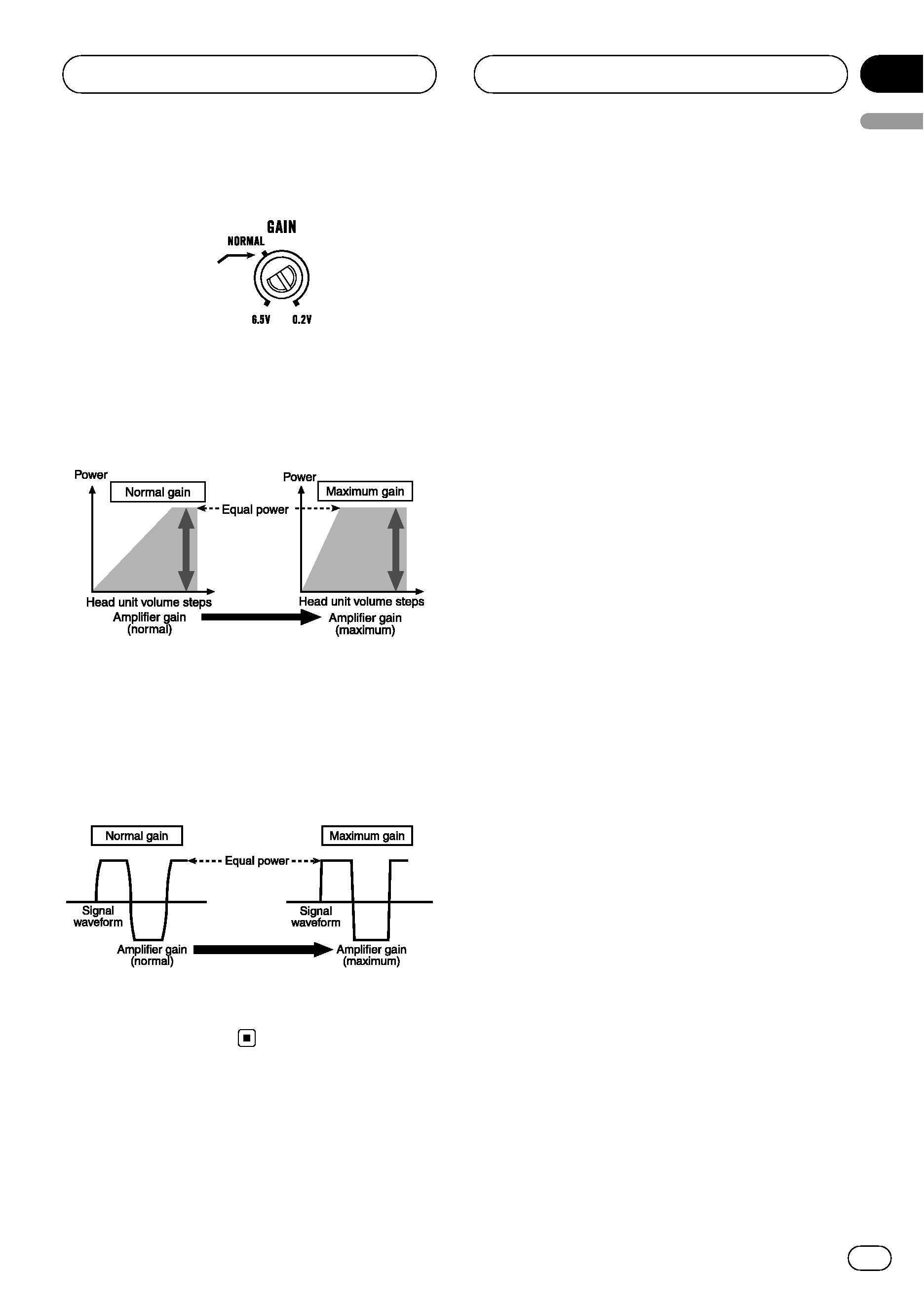
4 GAIN (gain) control
If output remains low, even when the car
stereo volume is turned up, turn controls to
lower level. If distortion occurs when the car
stereo volume is turned up, turn these con-
trols to higher level.
! For use with an RCA equipped car stereo
(standard output of 500 mV), set to the
NORMAL position. For use with an RCA
equipped Pioneer car stereo, with max.
output of 4 V or more, adjust level to
match that of the car stereo output.
! If you hear too much noise when using
the speaker input terminals, turn the
gain control to higher level.
5 LPF (low-pass filter) switch
Switch the settings based on the connected
speaker.
! When the Subwoofer is connected:
Select
ON. This eliminates high range
frequency and outputs low range fre-
quency.
! When the full range speaker is con-
nected:
Select
OFF. OFF outputs the entire fre-
quency range.
Setting gain properly
! Protective function included to prevent
malfunction of the unit and/or speakers
due to excessive output, improper use or
improper connection.
! When outputting high volume sound etc.,
this function cuts off the output for a few
seconds as a normal function, but output
is restored when the volume of the head
unit is turned down.
! A cut in sound output may indicate impro-
per setting of the gain control. To ensure
continuous sound output with the head
unit at a high volume, set amplifier gain
control to a level appropriate for the preout
maximum output level of the head unit, so
that volume can remain unchanged and to
control excess output.
! Despite correct volume and gain settings,
the unit sound still cuts out periodically. In
such cases, please contact the nearest
authorized Pioneer Service Station.
Setting the Unit
En
4
Section
02
background image
Gain control of this unit
Preout level: 2 V
(Standard: 500mV)
Above illustration shows
NORMAL gain set-
ting.
Relationship between amplifier gain
and head unit output power
If amplifier gain is raised improperly, this will
simply increase distortion, with little increase
in power.
Signal waveform when outputting at
high volume using amplifier gain
control
Signal waveform distorted with high output, if
you raise the gain of the amplifier the power
changes only slightly.
Setting the Unit
En
5
English
Section
02

Reviews

There are no reviews of this manual yet.