5
5
6
7
8
F
E
D
C
B
A
5
6
7
8
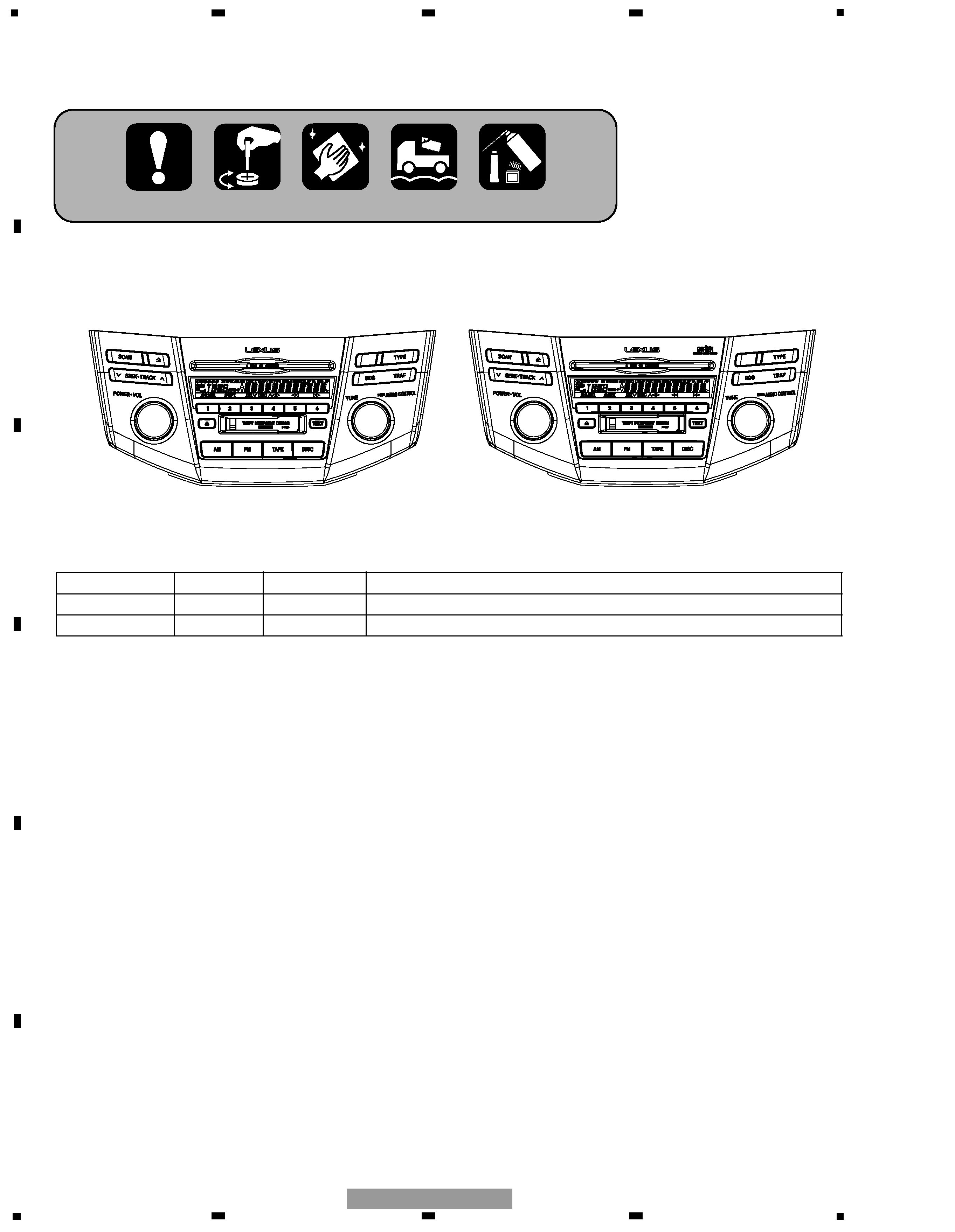
FX-MG8227ZT/UC
CONTENTS
SAFETY INFORMATION ......................................................................................................................................................3
1. SPECIFICATIONS .................................................................................................................................................................6
2. EXPLODED VIEWS AND PARTS LIST ................................................................................................................................7
2.1 PACKING(FX-MG8227ZT-91/UC, FX-MG8327ZT-91/UC) .............................................................................................7
2.2 EXTERIOR ......................................................................................................................................................................8
2.3 CD MECHANISM UNIT(1) ...........................................................................................................................................12
2.4 CD MECHANISM UNIT(2) ...........................................................................................................................................14
2.5 CASSETTE MECHANISM MODULE ...........................................................................................................................16
3. BLOCK DIAGRAM AND SCHEMATIC DIAGRAM.............................................................................................................19
3.1 BLOCK DIAGRAM(1) ...................................................................................................................................................19
3.2 BLOCK DIAGRAM(2) ...................................................................................................................................................20
3.3 OVERALL CONNECTION DIAGRAM(GUIDE PAGE) ..................................................................................................22
3.4 KEYBOARD UNIT.........................................................................................................................................................28
3.5 CD MECHANISM MODULE(GUIDE PAGE) ................................................................................................................30
3.6 CASSETTE MECHANISM MODULE ...........................................................................................................................40
4. PCB CONNECTION DIAGRAM..........................................................................................................................................42
4.1 MAIN UNIT...................................................................................................................................................................42
4.2 KEYBOARD PCB ..........................................................................................................................................................46
4.3 CD MECHANISM MODULE.........................................................................................................................................48
4.4 CASSETTE MECHANISM MODULE ...........................................................................................................................54
4.5 RIGHT PCB, LEFT PCB.................................................................................................................................................56
5. ELECTRICAL PARTS LIST..................................................................................................................................................57
6. ADJUSTMENT ...................................................................................................................................................................66
6.1 CONNECTION DIAGRAM............................................................................................................................................66
6.2 AUDIO, TUNER ADJUSTMENT ..................................................................................................................................70
6.3 TEST MODE .................................................................................................................................................................72
6.4 CD ADJUSTMENT .......................................................................................................................................................73
6.5 CHECKING THE GRATING AFTER CHANGING THE PICKUP UNIT .........................................................................75
6.6 TEST MODE(CD) ..........................................................................................................................................................77
6.7 AVC-LAN DIAGNOSIS MODE .....................................................................................................................................81
7. GENERAL INFORMATION.................................................................................................................................................85
7.1 DIAGNOSIS..................................................................................................................................................................85
7.1.1 DISASSEMBLY..........................................................................................................................................................85
7.1.2 PCB LOCATIONS ......................................................................................................................................................90
7.1.3 CONNECTOR FUNCTION DESCRIPTION................................................................................................................91
7.2 PARTS...........................................................................................................................................................................92
7.2.1 IC................................................................................................................................................................................92
7.2.2 DISPLAY ....................................................................................................................................................................99
7.3 EXPLANATION...........................................................................................................................................................100
7.3.1 SYSTEM BLOCK DIAGRAM...................................................................................................................................100
7.3.2 OPERATIONAL FLOW CHART ...............................................................................................................................103
7.4 NOTES ON SERVICING .............................................................................................................................................104
7.4.1 CLEANING...............................................................................................................................................................104
7.4.2 FACTORY SETTINGS..............................................................................................................................................104
8. OPERATIONS ...................................................................................................................................................................105