PIONEER CORPORATION
4-1, Meguro 1-Chome, Meguro-ku, Tokyo 153-8654, Japan
PIONEER ELECTRONICS SERVICE INC.
P.O.Box 1760, Long Beach, CA 90801-1760 U.S.A.
PIONEER EUROPE NV
Haven 1087 Keetberglaan 1, 9120 Melsele, Belgium
PIONEER ELECTRONICS ASIACENTRE PTE.LTD. 253 Alexandra Road, #04-01, Singapore 159936
C PIONEER CORPORATION 2001
K-ZZU. MAY 2001 Printed in Japan
ORDER NO.
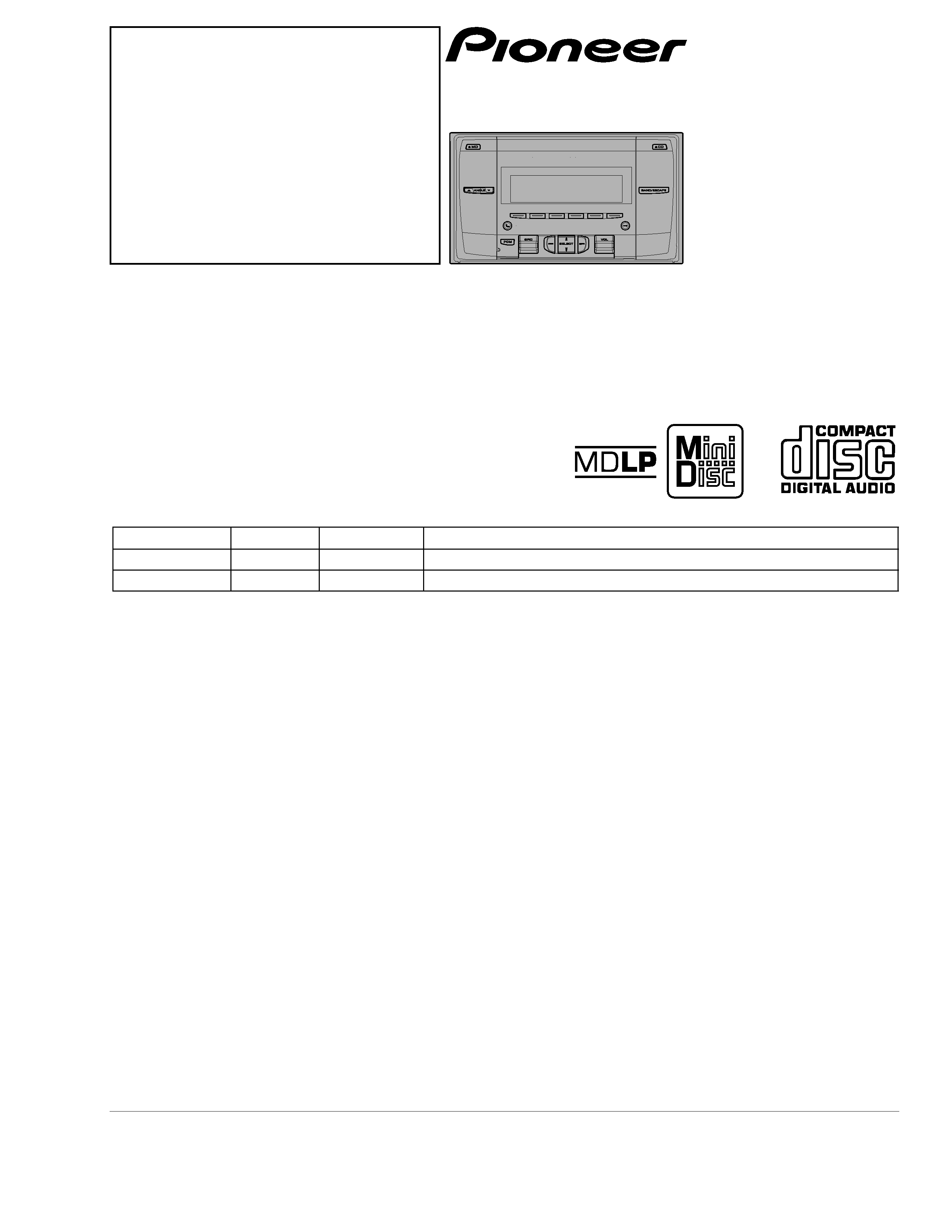
CRT2673
MULTI-CD/MD CONTROL DSP HIGH POWER CD MD PLAYER WITH FM/AM TUNER
FH-P8900MD
ES
CONTENTS
1. SAFETY INFORMATION ............................................2
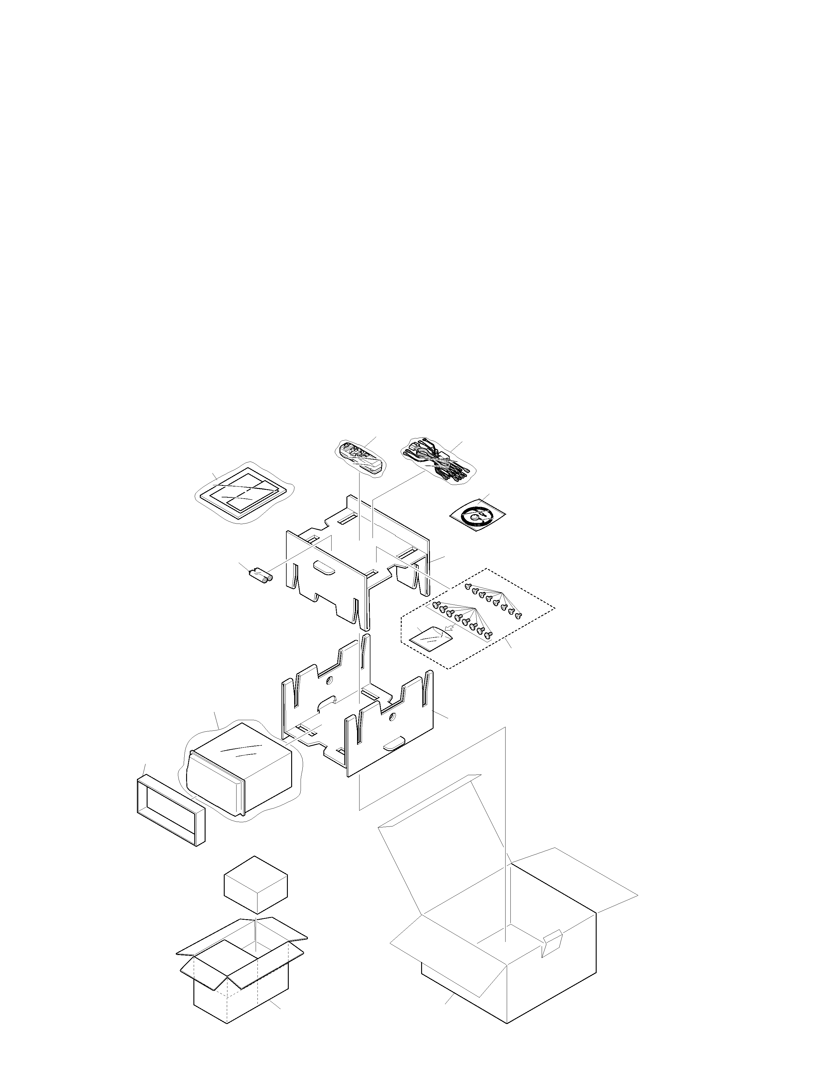
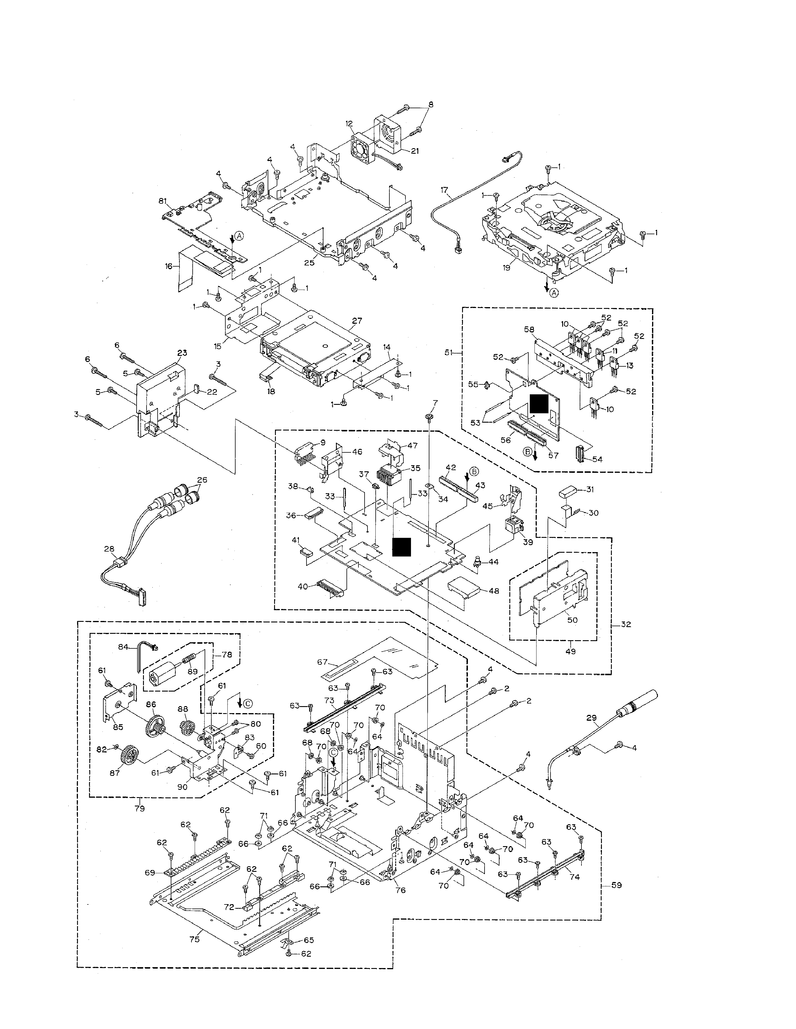
2. EXPLODED VIEWS AND PARTS LIST .......................2
3. BLOCK DIAGRAM AND SCHEMATIC DIAGRAM ...12
4. PCB CONNECTION DIAGRAM ................................40
5. ELECTRICAL PARTS LIST ........................................57
6. ADJUSTMENT..........................................................67
7. GENERAL INFORMATION .......................................78
7.1 DIAGNOSIS ........................................................78
7.1.1 ERROR CODE(CD) ....................................78
7.1.2 ERROR CODE(MD) ...................................82
7.1.3 DISASSEMBLY .........................................83
7.1.4 CONNECTOR FUNCTION DESCRIPTION .......90
7.2 IC ........................................................................91
7.3 OPERATIONAL FLOW CHART .........................105
8. OPERATIONS AND SPECIFICATIONS...................106
- This service manual should be used together with the following manual(s):
Model No.
Order No.
Mech. Module Remarks
CX-977
CRT2624
S9
CD Mech. Module:Circuit Description, Mech.Description, Disassembly
CX-1020
CRT2653
MD-4LP
MD Mech. Module:Circuit.Description, Mech.Description, Disassembly
- US and foreign patents licensed from Dolby Laboratories Licensing Corporation.
Service
Manual