PIONEER FH-P6100/XN/ES Service Manual

Cover page of PIONEER FH-P6100/XN/ES Service Manual

Service Manual for PIONEER FH-P6100/XN/ES, downloadable as a PDF file.

Manual details

  • Immediate download after payment.
  • Delivered as a PDF file.
  • The manual has 84 pages
  • File size: 9.98 MB
  • Available language versions: English
  • Different language versions may vary sligthly in file size and page count.

We guarantee that...

  • our manuals are complete,
  • the manual includes circuit diagrams,
  • our manuals are checked with antivirus,
  • We'll issue refund if the manual is damaged, incomplete or unreadable (our refund policy)

Sample pages

Thumbnail of page 1Thumbnail of page 2Thumbnail of page 3Thumbnail of page 4
Thumbnail of page 5Thumbnail of page 6Thumbnail of page 7Thumbnail of page 8
Thumbnail of page 9
background image
ORDER NO.
PIONEER CORPORATION 4-1, Meguro 1-chome, Meguro-ku, Tokyo 153-8654, Japan
PIONEER ELECTRONICS (USA) INC. P.O. Box 1760, Long Beach, CA 90801-1760, U.S.A.
PIONEER EUROPE NV Haven 1087, Keetberglaan 1, 9120 Melsele, Belgium
PIONEER ELECTRONICS ASIACENTRE PTE. LTD. 253 Alexandra Road, #04-01, Singapore 159936
PIONEER CORPORATION 2002
FH-P6100/XN/ES
CRT2826
MULTI-CD CONTROL DSP HIGH POWER CD CASSETTE PLAYER WITH FM/AM TUNER
FH-P6100
XN/ES
This service manual should be used together with the following manual(s):
Dolby noise reduction manufactured under license from Dolby Laboratories Licensing Corpora-
tion.
"Dolby" and the double-D symbol are trademarks of Dolby Laboratories Licensing Corporation.
CD section precaution
1. Before disassembling the unit, be sure to turn off the power. Unplugging and plugging the con-
nectors during power-on mode may damage the ICs inside the unit.
2. To protect the pickup unit from electrostatic discharge during servicing, take an appropriate
treatment (shorting-solder) by referring to "the DISASSEMBLY" on page 66.
3. After replacing the pickup unit, be sure to check the grating. (See p.61.)
Model No.
Order No.
Mech.Module
Remarks
CX-977
CRT2624
S9
CD Mech. Module:Circuit Description, Mech.Description, Disassembly
CX-1011
CRT2406
3L
Cassette Mech. Module:Mech.Description, Disassembly, Adjustment
For details, refer to "Important symbols for good services".
K-ZZU.APR.2002.printed in Japan
background image
FH-P6100/XN/ES
A
B
C
D
12
34
12
3
4
2
[ Important symbols for good services ]
In this manual, the symbols shown-below indicate that adjustments, settings or cleaning should be made securely.
When you find the procedures bearing any of the symbols, be sure to fulfill them:
2. Adjustments
To keep the original performances of the product, optimum adjustments or specification confirmation is indispensable.
In accordance with the procedures or instructions described in this manual, adjustments should be performed.
3. Cleaning
For optical pickups, tape-deck heads, lenses and mirrors used in projection monitors, and other parts requiring cleaning,
proper cleaning should be performed to restore their performances.
5. Lubricants, glues, and replacement parts
Appropriately applying grease or glue can maintain the product performances. But improper lubrication or applying
glue may lead to failures or troubles in the product. By following the instructions in this manual, be sure to apply the
prescribed grease or glue to proper portions by the appropriate amount.For replacement parts or tools, the prescribed
ones should be used.
4. Shipping mode and shipping screws
To protect the product from damages or failures that may be caused during transit, the shipping mode should be set or
the shipping screws should be installed before shipping out in accordance with this manual, if necessary.
1. Product safety
You should conform to the regulations governing the product (safety, radio and noise, and other regulations), and
should keep the safety during servicing by following the safety instructions described in this manual.
background image
FH-P6100/XN/ES
A
B
C
D
56
7
8
56
7
8
3
SAFETY INFORMATION
This service manual is intended for qualified service technicians; it is not meant for the
casual do-it-yourselfer.
Qualified technicians have the necessary test equipment and tools,and have been trained
to properly and safely repair complex products such as those covered by this manual.
Improperly performed repairs can adversely affect the safety and reliability of the product
and may void the warranty.
If you are not qualified to perfrom the repair of this product properly and safely, you
should not risk trying to do so and refer the repair to a qualified service technician.
background image
FH-P6100/XN/ES
A
B
C
D
12
34
12
3
4
4
CONTENTS
SAFETY INFORMATION . . . . . . . . . . . . . . . . . . . . . . . . . . . . . . . . . . . . . . . . . 3
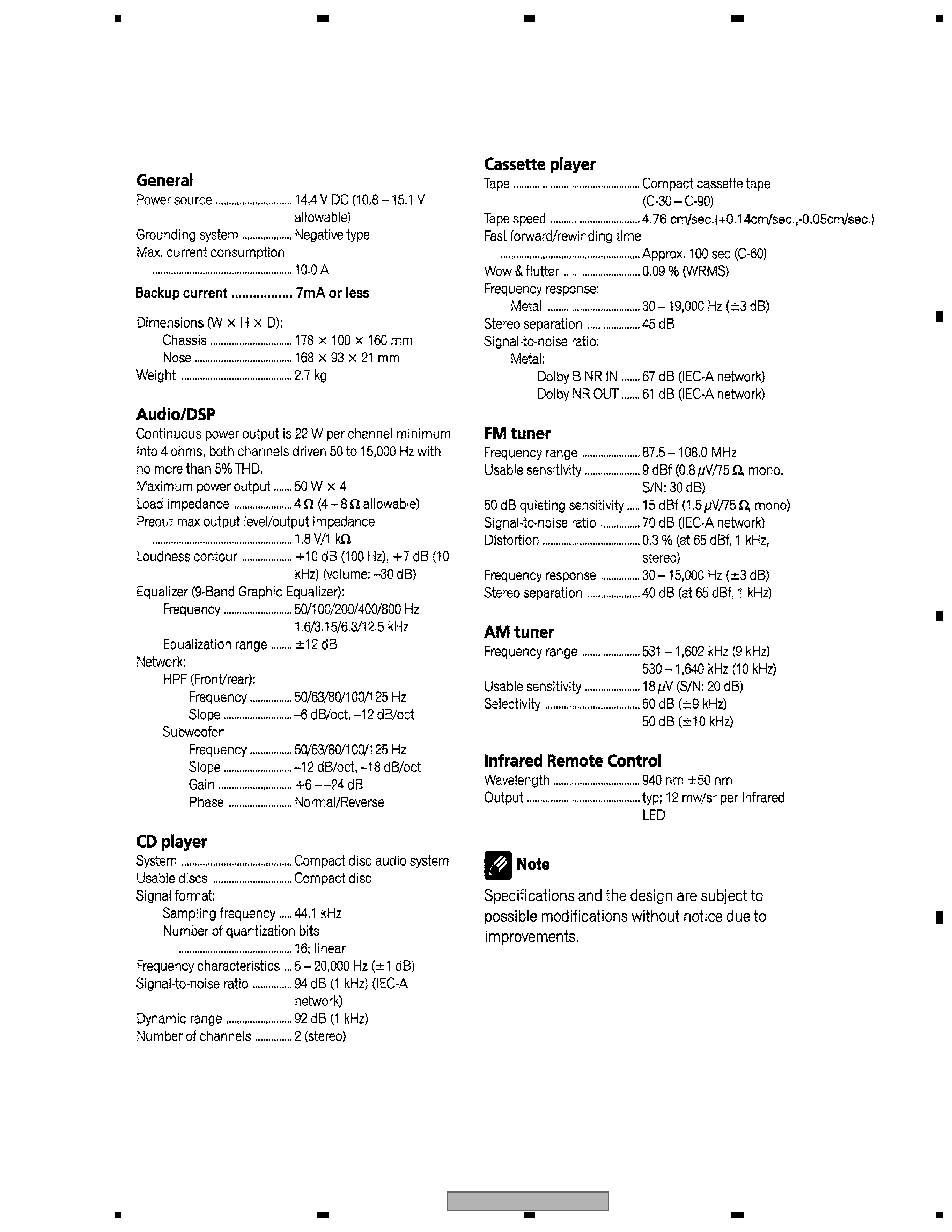
1. SPECIFICATIONS . . . . . . . . . . . . . . . . . . . . . . . . . . . . . . . . . . . . . . . . . . . 5
2. EXPLODED VIEWS AND PARTS LIST . . . . . . . . . . . . . . . . . . . . . . . . . . . . . . . . 6
2.1 PACKING . . . . . . . . . . . . . . . . . . . . . . . . . . . . . . . . . . . . . . . . . . . . . 6
2.2 EXTERIOR(1) . . . . . . . . . . . . . . . . . . . . . . . . . . . . . . . . . . . . . . . . . . . 8
2.3 EXTERIOR(2) . . . . . . . . . . . . . . . . . . . . . . . . . . . . . . . . . . . . . . . . . . 10
2.4 CD MECHANISM MODULE . . . . . . . . . . . . . . . . . . . . . . . . . . . . . . . . . . . 12
2.5 CASSETTE MECHANISM MODULE . . . . . . . . . . . . . . . . . . . . . . . . . . . . . . 14
3. BLOCK DIAGRAM AND SCHEMATIC DIAGRAM . . . . . . . . . . . . . . . . . . . . . . . . . . 16
3.1 BLOCK DIAGRAM . . . . . . . . . . . . . . . . . . . . . . . . . . . . . . . . . . . . . . . . 16
3.2 OVERALL CONNECTION DIAGRAM(GUIDE PAGE) . . . . . . . . . . . . . . . . . . . . . . 18
3.3 PCB UNIT . . . . . . . . . . . . . . . . . . . . . . . . . . . . . . . . . . . . . . . . . . . . 24
3.4 PANEL PCB UNIT . . . . . . . . . . . . . . . . . . . . . . . . . . . . . . . . . . . . . . . . 26
3.5 CD MECHANISM MODULE . . . . . . . . . . . . . . . . . . . . . . . . . . . . . . . . . . . 28
3.6 CASSETTE MECHANISM MODULE . . . . . . . . . . . . . . . . . . . . . . . . . . . . . . 32
4. PCB CONNECTION DIAGRAM . . . . . . . . . . . . . . . . . . . . . . . . . . . . . . . . . . . 34
4.1 AUDIO AMP UNIT . . . . . . . . . . . . . . . . . . . . . . . . . . . . . . . . . . . . . . . . 34
4.2 KEYBOARD PCB . . . . . . . . . . . . . . . . . . . . . . . . . . . . . . . . . . . . . . . . 38
4.3 LED_R PCB,LED_L PCB . . . . . . . . . . . . . . . . . . . . . . . . . . . . . . . . . . . . 40
4.4 PANEL PCB UNIT . . . . . . . . . . . . . . . . . . . . . . . . . . . . . . . . . . . . . . . . 42
4.5 CD MECHANISM MODULE . . . . . . . . . . . . . . . . . . . . . . . . . . . . . . . . . . . 44
4.6 CASSETTE MECHANISM MODULE . . . . . . . . . . . . . . . . . . . . . . . . . . . . . . 46
5. ELECTRICAL PARTS LIST . . . . . . . . . . . . . . . . . . . . . . . . . . . . . . . . . . . . . 48
6. ADJUSTMENT . . . . . . . . . . . . . . . . . . . . . . . . . . . . . . . . . . . . . . . . . . . . 57
6.1 CONTRAST ADJUSTMENT . . . . . . . . . . . . . . . . . . . . . . . . . . . . . . . . . . . 57
6.2 CASSETTE ADJUSTMENT . . . . . . . . . . . . . . . . . . . . . . . . . . . . . . . . . . . 58
6.3 CD ADJUSTMENT. . . . . . . . . . . . . . . . . . . . . . . . . . . . . . . . . . . . . . . . 59
6.4 CHECKING THE GRATING AFTER CHANGING THE PICKUP UNIT . . . . . . . . . . . . . 61
6.5 TEST MODE . . . . . . . . . . . . . . . . . . . . . . . . . . . . . . . . . . . . . . . . . . . 63
7. GENERAL INFORMATION . . . . . . . . . . . . . . . . . . . . . . . . . . . . . . . . . . . . . . 66
7.1 DIAGNOSIS . . . . . . . . . . . . . . . . . . . . . . . . . . . . . . . . . . . . . . . . . . . 66
7.1.1 DISASSEMBLY . . . . . . . . . . . . . . . . . . . . . . . . . . . . . . . . . . . . . . . . 66
7.1.2 CONNECTOR FUNCTION DESCRIPTION . . . . . . . . . . . . . . . . . . . . . . . . . . 71
7.2 PARTS . . . . . . . . . . . . . . . . . . . . . . . . . . . . . . . . . . . . . . . . . . . . . . 72
7.2.1 IC . . . . . . . . . . . . . . . . . . . . . . . . . . . . . . . . . . . . . . . . . . . . . . . 72
7.2.2 DISPLAY . . . . . . . . . . . . . . . . . . . . . . . . . . . . . . . . . . . . . . . . . . . . 79
7.3 OPERATIONAL FLOW CHART . . . . . . . . . . . . . . . . . . . . . . . . . . . . . . . . . 81
7.4 CLEANING. . . . . . . . . . . . . . . . . . . . . . . . . . . . . . . . . . . . . . . . . . . . 81
8. OPERATIONS . . . . . . . . . . . . . . . . . . . . . . . . . . . . . . . . . . . . . . . . . . . . 82
background image
FH-P6100/XN/ES
A
B
C
D
56
7
8
56
7
8
5
1. SPECIFICATIONS

Reviews

There are no reviews of this manual yet.