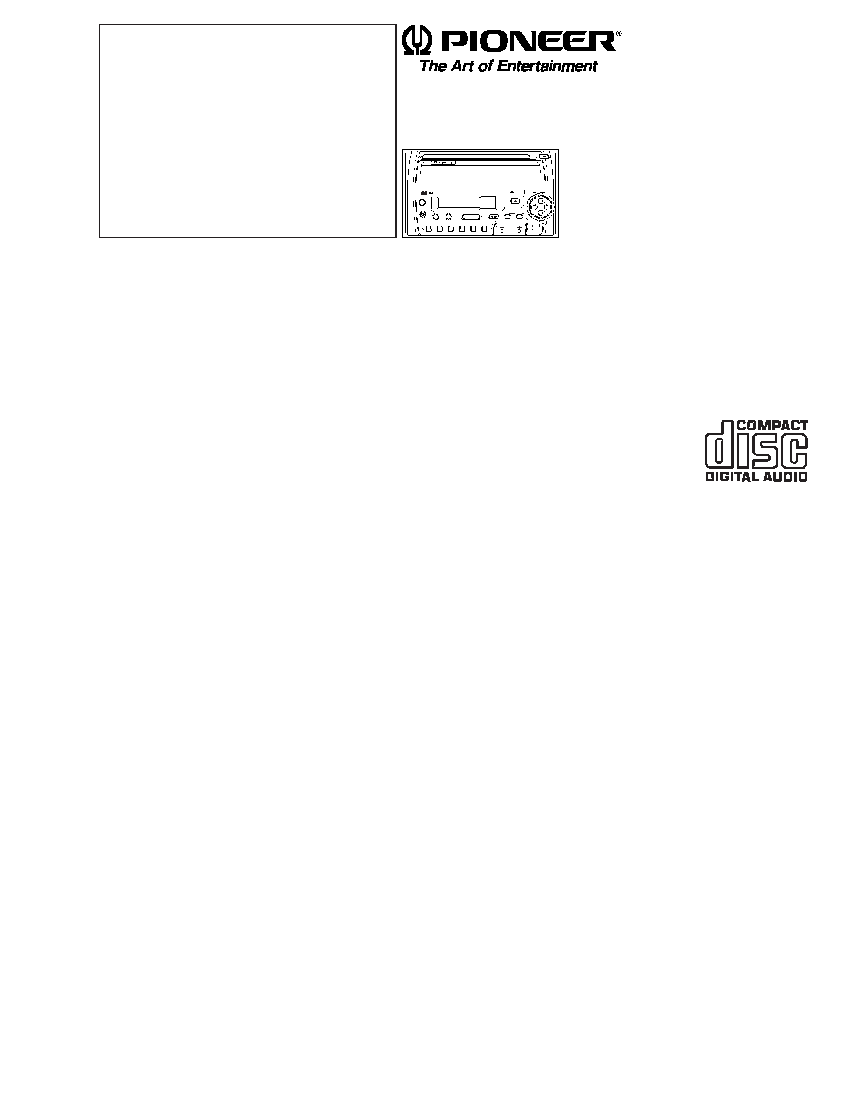
MULTI-CD/MD CONTROL TUNER CD DECK AMPLIFIER
FH-P404
UC
Service
Manual
FH-P404
ES
FH-P404/UC
PGM
ATT
DISPLAY
CLOCK
ESC
BAND
AUDIO
TRK
/ SEEK
DISC
/ CH
FUNCTION
SEL
DIRECT EQ
VOLUME
OFF
SOURCE
AF
D
S/A
16
5
4
3
2
P
CD
EJECT
HIGH POWER 40Wx4
CD TUNER DECK AMP
FH-P404
EJECT
AUTOMATIC CASSETTE LOADING & EJECTION
DOLBY B NR
PIONEER ELECTRONIC CORPORATION
4-1, Meguro 1-Chome, Meguro-ku, Tokyo 153-8654, Japan
PIONEER ELECTRONICS SERVICE INC.
P.O.Box 1760, Long Beach, CA 90801-1760 U.S.A.
PIONEER ELECTRONIC [EUROPE] N.V.
Haven 1087 Keetberglaan 1, 9120 Melsele, Belgium
PIONEER ELECTRONICS ASIACENTRE PTE.LTD. 501 Orchard Road, #10-00, Lane Wheelock Place, Singapore 23880
C PIONEER ELECTRONIC CORPORATION 1998
ORDER NO.
CRT2247
CONTENTS
1. SAFETY INFORMATION ............................................2
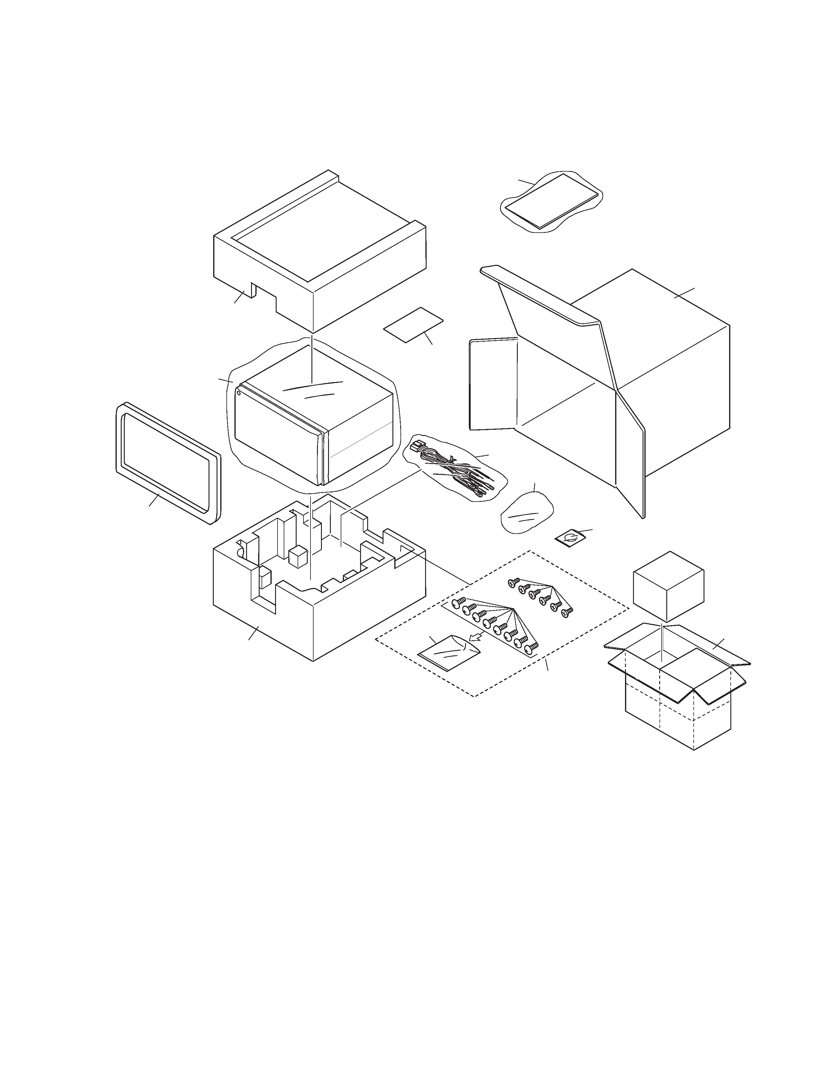
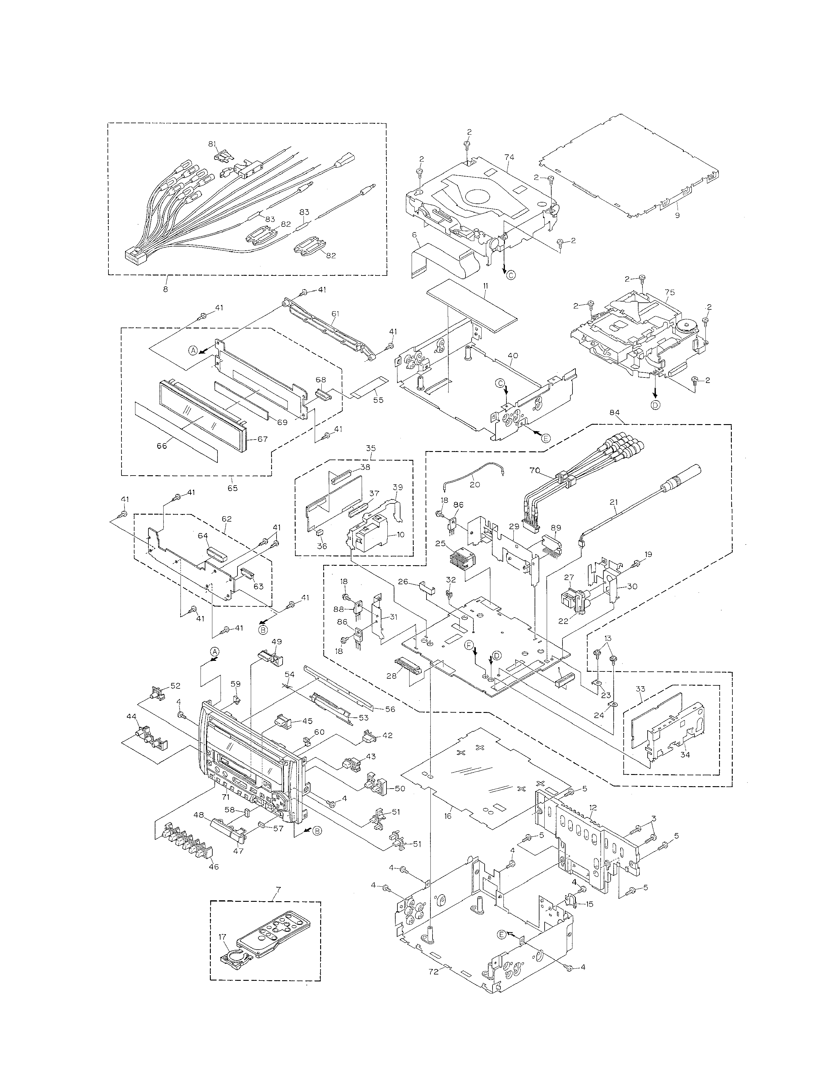
2. EXPLODED VIEWS AND PARTS LIST .......................3
3. SCHEMATIC DIAGRAM ...........................................12
4. PCB CONNECTION DIAGRAM ................................38
5. ELECTRICAL PARTS LIST ........................................52
6. ADJUSTMENT..........................................................62
7. GENERAL INFORMATION .......................................68
7.1 PARTS .................................................................68
7.1.1 IC................................................................68
7.1.2 DISPLAY ....................................................75
7.2 DISASSEMBLY ...................................................79
7.3 BLOCK DIAGRAM ..............................................80
8. OPERATIONS AND SPECIFICATIONS.....................82
- See the separate manual CX-597(CRT1829) for the CD mechanism description, disassembly and circuit
description.
- The CD mechanism employed in this model is one of S7 series.
- See the separate manual CX-631(CRT1640) for the cassette mechanism description, disassembly and
circuit description.
- The cassette mechanism employed in this model is one of 2L series.
- Dolby noise reduction manufactured under license from Dolby Laboratories Licensing Corporation.
"Dolby" and the double-D symbol are trademarks of Dolby Laboratories Licensing Corporation.
K-ZZB. AUG. 1998 Printed in Japan