PIONEER DV-U7/WYXJ Service Manual

Cover page of PIONEER DV-U7/WYXJ Service Manual

Service Manual for PIONEER DV-U7/WYXJ, downloadable as a PDF file.

We also have owner's manual to this model.

Manual details

  • Immediate download after payment.
  • Delivered as a PDF file.
  • The manual has 93 pages
  • File size: 5.66 MB
  • Available language versions: English
  • Different language versions may vary sligthly in file size and page count.

We guarantee that...

  • our manuals are complete,
  • the manual includes circuit diagrams,
  • our manuals are checked with antivirus,
  • We'll issue refund if the manual is damaged, incomplete or unreadable (our refund policy)

Sample pages

Thumbnail of page 1Thumbnail of page 2Thumbnail of page 3Thumbnail of page 4
Thumbnail of page 5Thumbnail of page 6Thumbnail of page 7Thumbnail of page 8
Thumbnail of page 9
background image
PIONEER CORPORATION 4-1, Meguro 1-chome, Meguro-ku, Tokyo 153-8654, Japan
PIONEER ELECTRONICS (USA) INC. P.O. Box 1760, Long Beach, CA 90801-1760, U.S.A.
PIONEER EUROPE NV Haven 1087, Keetberglaan 1, 9120 Melsele, Belgium
PIONEER ELECTRONICS ASIACENTRE PTE. LTD. 253 Alexandra Road, #04-01, Singapore 159936
PIONEER CORPORATION 2002
c
ORDER NO.
DV-U7
RRV2626
T ­ IZE JUNE 2002 Printed in Japan
DVD PLAYER
For details, refer to "Important symbols for good services".
8
41
¡ ¢
OPEN/CLOSE
STANDBY/ON
0
Î
DV-U7
Model
Type
Power Requirement
Region No.
The voltage can be converted
by the following method
Remarks
DV-U7
WYXJ
AC220 - 240V
2
Automatic select
DV-U7
RLXJ/NC
AC110 - 127V / 220 - 240V
3
Automatic select
DV-U7
RDXJ/RD
AC110 - 127V / 220 - 240V
4
Automatic select
THIS MANUAL IS APPLICABLE TO THE FOLLOWING MODEL(S) AND TYPE(S).
background image
2
DV-U7
12
3
4
C
D
F
A
B
E
1
23
4
SAFETY INFORMATION
This service manual is intended for qualified service technicians ; it is not meant for the casual
do-it-yourselfer. Qualified technicians have the necessary test equipment and tools, and have been
trainedto properly and safely repair complex products such as those covered by this
manual.Improperly performed repairs can adversely affect the safety and reliability of the product
and mayvoid the warranty. If you are not qualified to perform the repair of this product properly and
safely, youshould not risk trying to do so and refer the repair to a qualified service technician.
WARNING !
THE AEL (ACCESSIBLE EMISSION LEVEL) OF THE LASER POWER OUTPUT IS LESS THAN CLASS 1
BUT THE LASER COMPONENT IS CAPABLE OF EMITTING RADIATION EXCEEDING THE LIMIT FOR
CLASS 1.
A SPECIALLY INSTRUCTED PERSON SHOULD DO SERVICING OPERATION OF THE APPARATUS.
LASER DIODE CHARACTERISTICS
FOR DVD : MAXIMUM OUTPUT POWER : 5 mW
WAVELENGTH : 650 nm
FOR CD :
MAXIMUM OUTPUT POWER : 5 mW
WAVELENGTH : 780 nm
Additional Laser Caution
: See page 48.
1. Laser Interlock Mechanism
· Loading switch (S101 on the LOAB Assy) is used for interlock
mechanism of the laser.
When this switch turned ON in SW2 (XCLOSE) side (OPEN signal is
0V and XCLOSE signal is 3.5V), a laser becomes the status which
can completely oscillation.
Furthermore, the laser completely oscillates in the disc judgment and
disc playback.
When player is power ON state and laser diode is not completely
oscillating, 780nm laser diode is always oscillating by half power.
· Laser diode is driving with Q101 (650nm LD) and Q102 (780nm LD)
on the DVDM Assy.
Therefore, when short-circuit between the emitter and collector of
these transistors or the base voltage is supplied for transistors turn
on, the laser oscillates. (failure mode)
· In the test mode
, there is the mode that the laser oscillates except
for the disc judgment and playback. LD ON mode in the test mode
oscillates with the laser forcibly.
The interlock mechanism mentioned above becomes invalid in this
mode.
2. When the cover is open, close viewing through the objective lens with
the naked eye will cause exposure to the laser beam.
LABEL CHECK
DV-U7/WYXJ
Only
(Printed on the Bottom Case)
background image
3
DV-U7
5
67
8
5
6
7
8
C
D
F
A
B
E
[ Important symbols for good services ]
In this manual, the symbols shown-below indicate that adjustments, settings or cleaning should be made securely.
When you find the procedures bearing any of the symbols, be sure to fulfill them:
2. Adjustments
To keep the original performances of the product, optimum adjustments or specification confirmation is indispensable.
In accordance with the procedures or instructions described in this manual, adjustments should be performed.
3. Cleaning
For optical pickups, tape-deck heads, lenses and mirrors used in projection monitors, and other parts requiring cleaning,
proper cleaning should be performed to restore their performances.
5. Lubricants, glues, and replacement parts
Appropriately applying grease or glue can maintain the product performances. But improper lubrication or applying
glue may lead to failures or troubles in the product. By following the instructions in this manual, be sure to apply the
prescribed grease or glue to proper portions by the appropriate amount.For replacement parts or tools, the prescribed
ones should be used.
4. Shipping mode and shipping screws
To protect the product from damages or failures that may be caused during transit, the shipping mode should be set or
the shipping screws should be installed before shipping out in accordance with this manual, if necessary.
1. Product safety
You should conform to the regulations governing the product (safety, radio and noise, and other regulations), and
should keep the safety during servicing by following the safety instructions described in this manual.
Discs compatible with this
player
Any disc that displays one of the following
logos should play in this player. Other
formats, including DVD-Audio, DVD-RAM,
DVD-ROM, CD-ROM (except those that
contain MP3 files), SACD and Photo CD will
not play.
Audio-CD
DVD-Video
Video-CD
CD-R
CD-RW
: Video Mode Only.
background image
4
DV-U7
12
3
4
C
D
F
A
B
E
1
23
4
CONTENTS
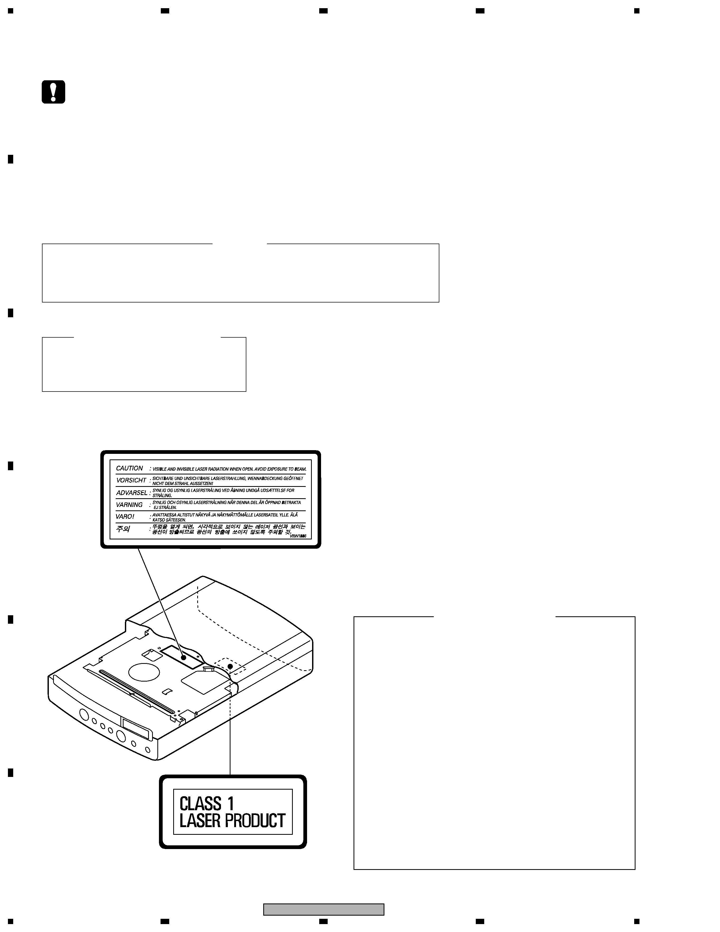
SAFETY INFORMATION ......................................................................................................................................2
1. SPECIFICATIONS ............................................................................................................................................5
1.1 WYXJ Type .................................................................................................................................................5
1.2 RLXJ/NC and RDXJ/RD Types ................................................................................................................. 6
2. EXPLODED VIEWS AND PARTS LIST .......................................................................................................... 8
2.1 PACKING ....................................................................................................................................................8
2.2 EXTERIOR SECTION ............................................................................................................................. 10
2.3 LOADING MECHANISM ASSY ............................................................................................................... 12
2.4 TRAVERSE MECHANISM ASSY-S ........................................................................................................ 14
3. BLOCK DIAGRAM AND SCHEMATIC DIAGRAM ........................................................................................ 16
3.1 BLOCK DIAGRAM and WAVEFORMS ................................................................................................... 16
3.2 LOAB, SSIB ASSYS and OVERALL WIRING DIAGRAM ...................................................................... 20
3.3 DVDM ASSY (1/2) ................................................................................................................................... 22
3.4 DVDM ASSY (2/2) ................................................................................................................................... 24
3.5 JCKB ASSY (1/2) .................................................................................................................................... 26
3.6 JCKB (2/2), SCRB and COMP ASSYS ................................................................................................... 28
3.7 LEDB and FLKB ASSYS ........................................................................................................................ 30
3.8 POWER SUPPLY UNIT .......................................................................................................................... 32
4. PCB CONNECTION DIAGRAM ..................................................................................................................... 33
4.1 LOAB and SSIB ASSYS .......................................................................................................................... 33
4.2 DVDM ASSY ........................................................................................................................................... 34
4.3 JCKB ASSY ............................................................................................................................................. 38
4.4 LEDB and FLKB ASSYS ........................................................................................................................ 40
4.5 POWER SUPPLY UNIT .......................................................................................................................... 42
4.6 SCRB and COMP ASSYS ....................................................................................................................... 43
5. PCB PARTS LIST .......................................................................................................................................... 44
6. ADJUSTMENT ............................................................................................................................................... 48
7. GENERAL INFORMATION ............................................................................................................................ 54
7.1 DIAGNOSIS ............................................................................................................................................. 54
7.1.1 TEST MODE .................................................................................................................................... 54
7.1.2 DISPLAY OF THE MECHANISM ERROR HISTORY ..................................................................... 60
7.1.3 TROUBLE SHOOTING .................................................................................................................... 63
7.1.4 SEQUENCE AFTER POWER ON ...................................................................................................65
7.1.5 DISASSEMBLY ................................................................................................................................ 66
7.2 IC ............................................................................................................................................................. 70
7.3 CLEANING .............................................................................................................................................. 88
8. PANEL FACILITIES ....................................................................................................................................... 89
8.1 FRONT PANEL ....................................................................................................................................... 89
8.2 DISPLAY .................................................................................................................................................. 90
8.3 REAR PANEL .......................................................................................................................................... 91
8.4 REMOTE CONTROL UNIT ..................................................................................................................... 93
background image
5
DV-U7
5
67
8
5
6
7
8
C
D
F
A
B
E
1. SPECIFICATIONS
General
System.................................................................DVD player
Power requirements.......................AC 220 - 240V, 50/60 Hz
Power consumption.......................................................13 W
Power consumption (standby)....................................0.30 W
Weight..........................................................................1.8 kg
Dimensions...........................210 (W) x 65 (H) x 311 (D) mm
Operating temperature.................................+5
°C to +35°C
Operating humidity................................................5% to 85%
(no condensation)
S-Video output
Y (luminance) - Output level.............................1 Vp-p (75
)
C (color) - Output level..............................286 mVp-p (75
)
Jack....................................................................S-Video jack
Video output
Output level......................................................1 Vp-p (75
)
Jack.........................................................................RCA jack
AV connector output
AV Connector (21-pin connector assignment)
AV connector output....................................21-pin connector
This connector provides the video and audio signals for
connection to a compatible colour TV or monitor.
Audio output (1 stereo pair)
Output level............................................During audio output
200 mVrms (1 kHz,
-20 dB)
Jacks................................................RCA jack (1 stereo pair)
Digital audio characteristics
Frequency response.......................................4 Hz to 44 kHz
(DVD fs: 96 kHz)
S/N ratio......................................................................118 dB
Dynamic range............................................................101 dB
Total harmonic distortion.........................................0.0016 %
Wow and flutter...................................Limit of measurement
(
±0.001% W. PEAK) or lower
Digital output
Optical digital output .................................Optical digital jack
Accessories
Audio/video cable.................................................................1
Power cord...........................................................................1
Remote control unit..............................................................1
AA / R6P dry cell batteries...................................................2
Operating Instructions..........................................................1
Warranty card.......................................................................1
Note :
· The specifications and design of this product are subject
to change without notice, due to improvement.
Pin No.
1..........................Audio 2/R out
3...........................Audio 1/L out
4........................................GND
7........................................B out
8......................................Status
11.....................................G out
15.............................R or C out
17......................................GND
19.................Video out or Y out
21......................................GND
Accessories
Remote Control Unit
(VXX2805)
Audio / Video Cable
(XDE3049)
L = 1.5m
Dry Cell Battery (R6P/AA)
Power Cord
(ADG1154)
White
Yellow
Red
· Manufactured under license from Dolby Laboratories.
"Dolby" and the double-D symbol are trademarks of
Dolby Laboratories.
· "DTS" is a registered trademark of
DigitalTheater Systems, Inc.
· TruSurround and the
symbol are
trademarks of SRS Labs, Inc. TruSurround
technology is incorporated under license from
SRS Labs, Inc.
®
0
1
23
4
5
6
78
9
CLEAR
ENTER
ANGLE
AUDIO
TOP MENU
SETUP
SUBTITLE
PLAY MODE SURROUND ZOOM
DISPLAY
MENU
RETURN
ENTER
STANDBY/ON
OPEN/CLOSE
4
/
e
E/
1
¡
¢
8
7
3
0
1.1 WYXJ Type

Reviews

There are no reviews of this manual yet.