DVR-LX60D
4
12
34
1
234
C
D
F
A
B
E
CONTENTS
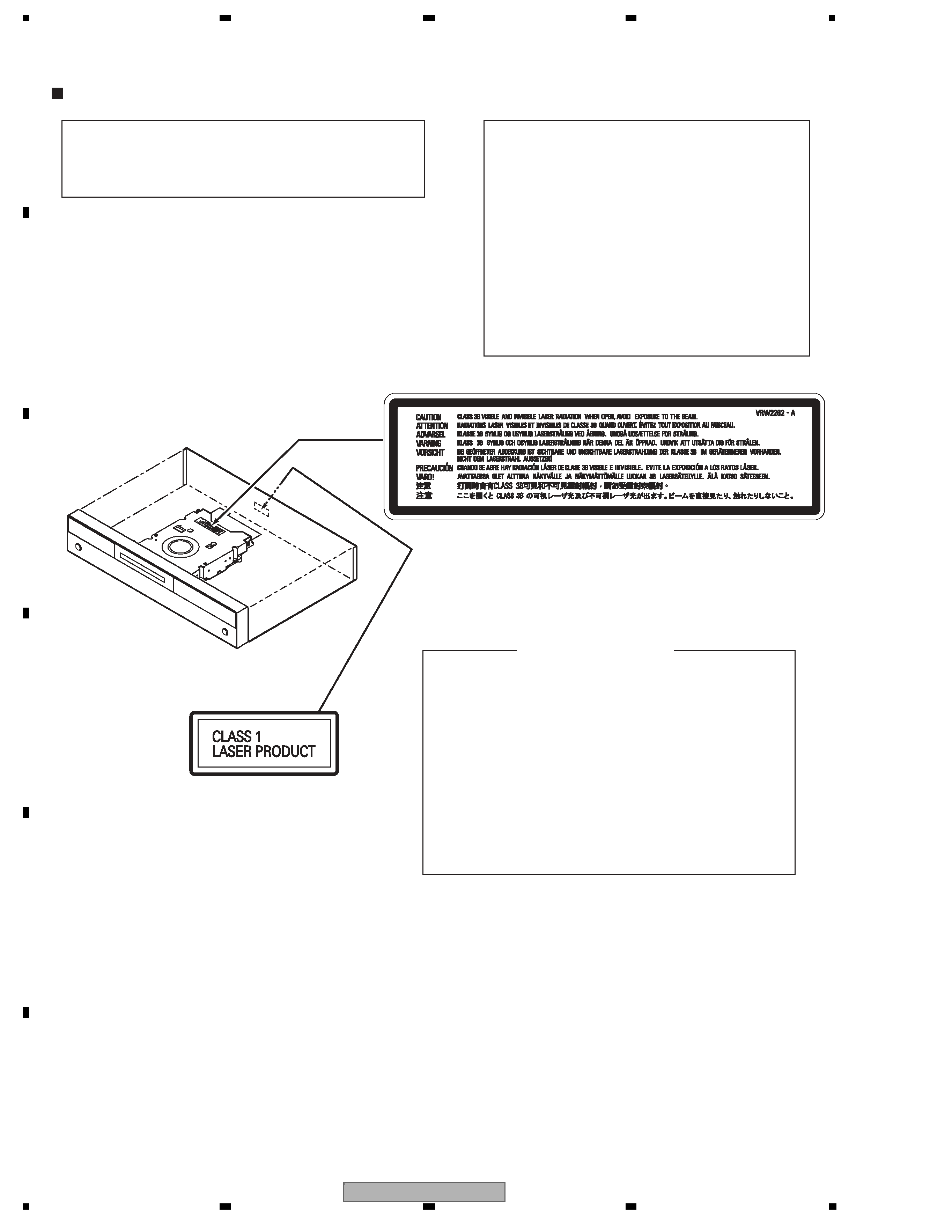
SAFETY INFORMATION..................................................................................................................................... 2
1. SERVICE PRECAUTIONS ............................................................................................................................... 6
1.1 NOTES ON SOLDERING .......................................................................................................................... 6
1.2 NOTES ON HANDLING THE HDD............................................................................................................ 7
1.3 NOTES ON REPLACEMENT OF THE SDRAM ........................................................................................ 9
1.4 NOTE ON INSULATORS AND THEIR SET SCREWS.............................................................................. 9
1.5 NOTES ON REPLACEMENT OF THE FL LENS..................................................................................... 10
1.6 NOTE ON PC CARDS ............................................................................................................................. 10
2. SPECIFICATIONS...........................................................................................................................................11
2.1 ACCESSORIES ........................................................................................................................................11
2.2 SPECIFICATIONS ................................................................................................................................... 12
2.3 DISC/CONTENT FORMAT ...................................................................................................................... 14
2.4 PANEL FACILITIES.................................................................................................................................. 19
3. BASIC ITEMS FOR SERVICE........................................................................................................................ 25
3.1 CHECK POINTS AFTER SERVICING..................................................................................................... 25
3.2 QUICK REFERENCE............................................................................................................................... 26
3.3 PCB LOCATIONS .................................................................................................................................... 27
3.4 JIGS LIST ................................................................................................................................................ 28
4. BLOCK DIAGRAM.......................................................................................................................................... 30
4.1 OVERALL WIRING DIAGRAM ................................................................................................................ 30
4.2 OVERALL BLOCK DIAGRAM.................................................................................................................. 32
4.3 POWER BLOCK DIAGRAM..................................................................................................................... 34
5. DIAGNOSIS.................................................................................................................................................... 35
5.1 SETUP SEQUENCE................................................................................................................................ 35
5.2 DIAGNOSIS OF THE MAIN ASSY .......................................................................................................... 36
5.3 DIAGNOSIS OF THE DTVD ASSY.......................................................................................................... 40
6. SERVICE MODE ............................................................................................................................................ 41
6.1 VERSION INFORMATION, ETC. (FIRST SCREEN) ............................................................................... 43
6.2 ATA/ATAPI DEBUG SCREEN (SECOND SCREEN) ............................................................................... 48
6.3 VR-RECORDING-RELATED ERROR LOGS (FOURTH SCREEN) ........................................................ 50
6.4 VR-PLAYBACK-RELATED ERROR LOGS (FIFTH SCREEN) ................................................................ 54
6.5 DV SERVICE MODE................................................................................................................................ 57
6.6 EPG SERVICE MODE ............................................................................................................................. 60
6.7 HDMI SERVICE MODE ........................................................................................................................... 62
6.8 AGING MODE.......................................................................................................................................... 64
6.9 USB CHECK MODE ................................................................................................................................ 66
6.10 HDD CHECK MODE .............................................................................................................................. 67
7. DISASSEMBLY .............................................................................................................................................. 73
8. EACH SETTING AND ADJUSTMENT ........................................................................................................... 78
8.1 MODEL SETTING.................................................................................................................................... 78
8.2 LD POWER ADJUSTMENT..................................................................................................................... 79
8.3 CPRM ID NUMBER AND DATA SETTING .............................................................................................. 83
8.4 FIRMWARE UPDATE METHOD.............................................................................................................. 87
8.5 VIDEO ADJUSTMENT FOR SPECIFIC AREA........................................................................................ 90
9. EXPLODED VIEWS AND PARTS LIST.......................................................................................................... 94
9.1 PACKING ................................................................................................................................................. 94
9.2 EXTERIOR SECTION.............................................................................................................................. 96
9.3 FRONT PANEL SECTION ....................................................................................................................... 98
9.4 SERVICE LOADER MAIN SECTION..................................................................................................... 102
10. SCHEMATIC DIAGRAM............................................................................................................................. 104
10.1 SERVICE TUSB ASSY (1/4)................................................................................................................ 104
10.2 SERVICE TUSB ASSY (2/4)................................................................................................................ 106
10.3 SERVICE TUSB ASSY (3/4)................................................................................................................ 108
10.4 SERVICE TUSB ASSY (4/4).................................................................................................................110
10.5 SERVICE FLKY and SERVICE FRJB ASSYS......................................................................................112
10.6 SERVICE MAIN ASSY (1/5) .................................................................................................................114
10.7 SERVICE MAIN ASSY (2/5) .................................................................................................................116
10.8 SERVICE MAIN ASSY (3/5) .................................................................................................................118
10.9 SERVICE MAIN ASSY (4/5) ................................................................................................................ 120
10.10 SERVICE MAIN ASSY (5/5) .............................................................................................................. 122
10.11 DTVD ASSY (1/4)............................................................................................................................... 124
10.12 DTVD ASSY (2/4) .............................................................................................................................. 126
10.13 DTVD ASSY (3/4) .............................................................................................................................. 128
10.14 DTVD ASSY (4/4) .............................................................................................................................. 130
10.15 SERVICE DVUB ASSY...................................................................................................................... 132