ORDER NO.
PIONEER CORPORATION 4-1, Meguro 1-chome, Meguro-ku, Tokyo 153-8654, Japan
PIONEER ELECTRONICS (USA) INC. P.O. Box 1760, Long Beach, CA 90801-1760, U.S.A.
PIONEER EUROPE NV Haven 1087, Keetberglaan 1, 9120 Melsele, Belgium
PIONEER ELECTRONICS ASIACENTRE PTE. LTD. 253 Alexandra Road, #04-01, Singapore 159936
PIONEER CORPORATION 2002
PHONES
BUSY
DVR-A05
RRV2706
DVD-R/RW CD-R/RW WRITER
DVR-A05
THIS MANUAL IS APPLICABLE TO THE FOLLOWING MODEL(S) AND TYPE(S).
CONTENTS
SAFETY INFORMATION................................................................................................................... 2
1. SPECIFICATIONS .......................................................................................................................... 4
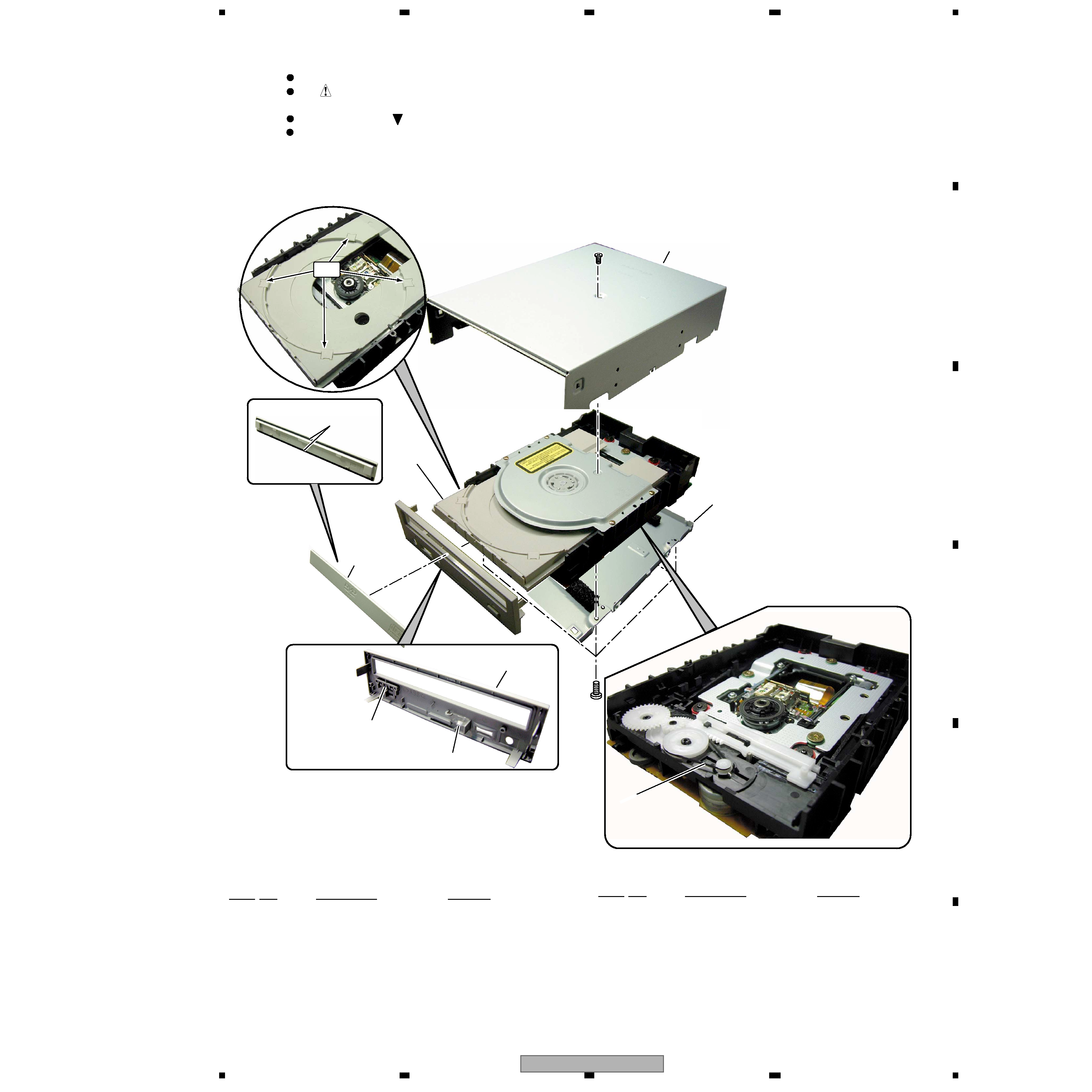
2. EXPLODED VIEWS AND PARTS LIST .......................................................................................... 5
2.1 EXTERIOR SECTION................................................................................................................ 5
3. GENERAL INFORMATION............................................................................................................. 6
3.1 DIAGNOSIS ............................................................................................................................... 6
3.1.1 EMERGENCY DISC REMOVAL .......................................................................................... 6
3.1.2 PICKUP LENS CLEANING.................................................................................................. 7
3.1.3 CLEANING .......................................................................................................................... 8
3.1.4 INSPECTION (FAULT ANALYSIS PROGRAM) METHOD................................................... 9
3.1.5 MEASUREMENT METHOD OF THE LASER DIODE DETERIORATION RATE............... 10
Model
Type
Power Requirement
Remarks
DVR-A05
KBXV
DC Power supply from other system
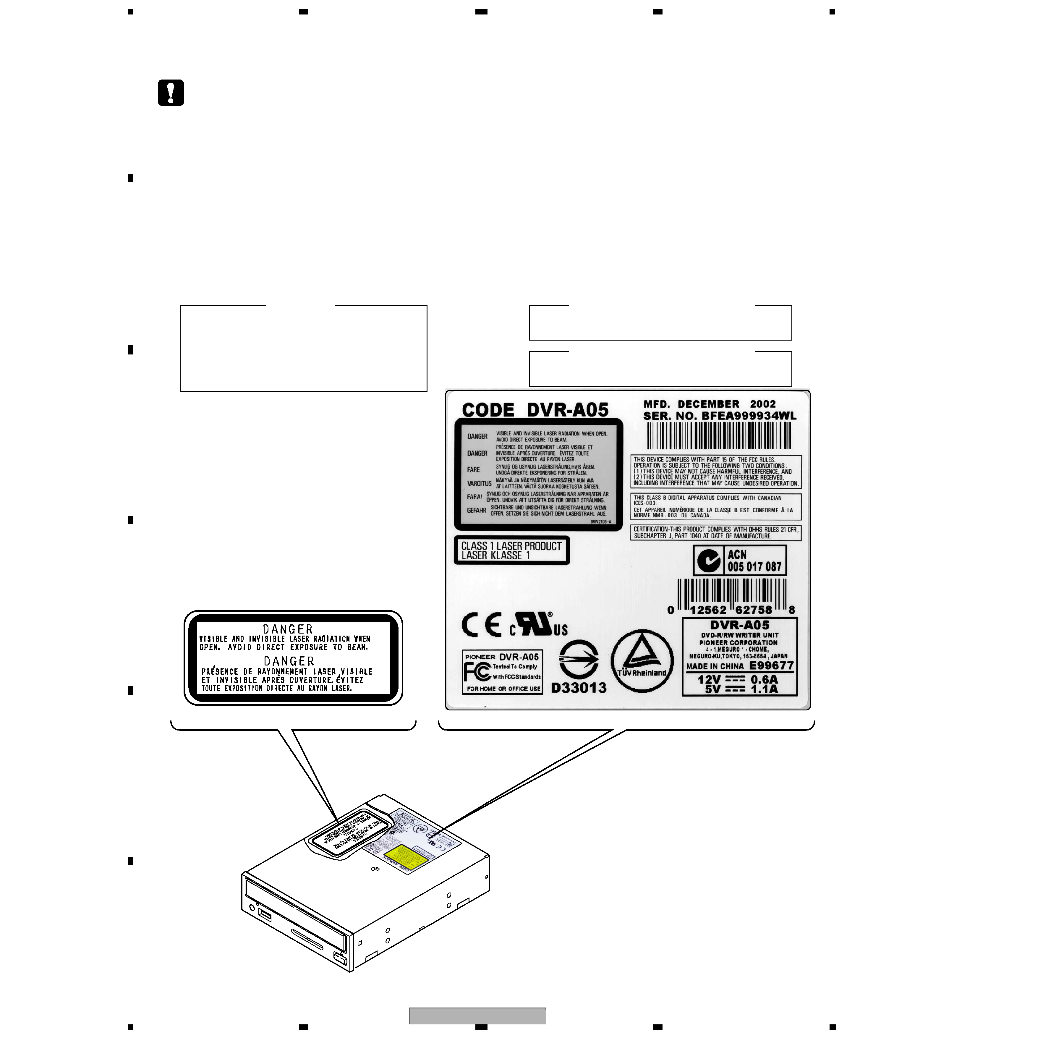
NECESSARY INFORMATION FOR DHHS RULES MARKED ON THE
TOP COVER BELOW:
DANGER-VISIBLE AND INVISIBLE LASER RADIATION WHEN OPEN.
AVOID DIRECT EXPOSURE TO BEAM.
For details, refer to "Important symbols for good services" on the next page.
T-ZZY OCT. 2002 printed in Japan