2
DVL-919
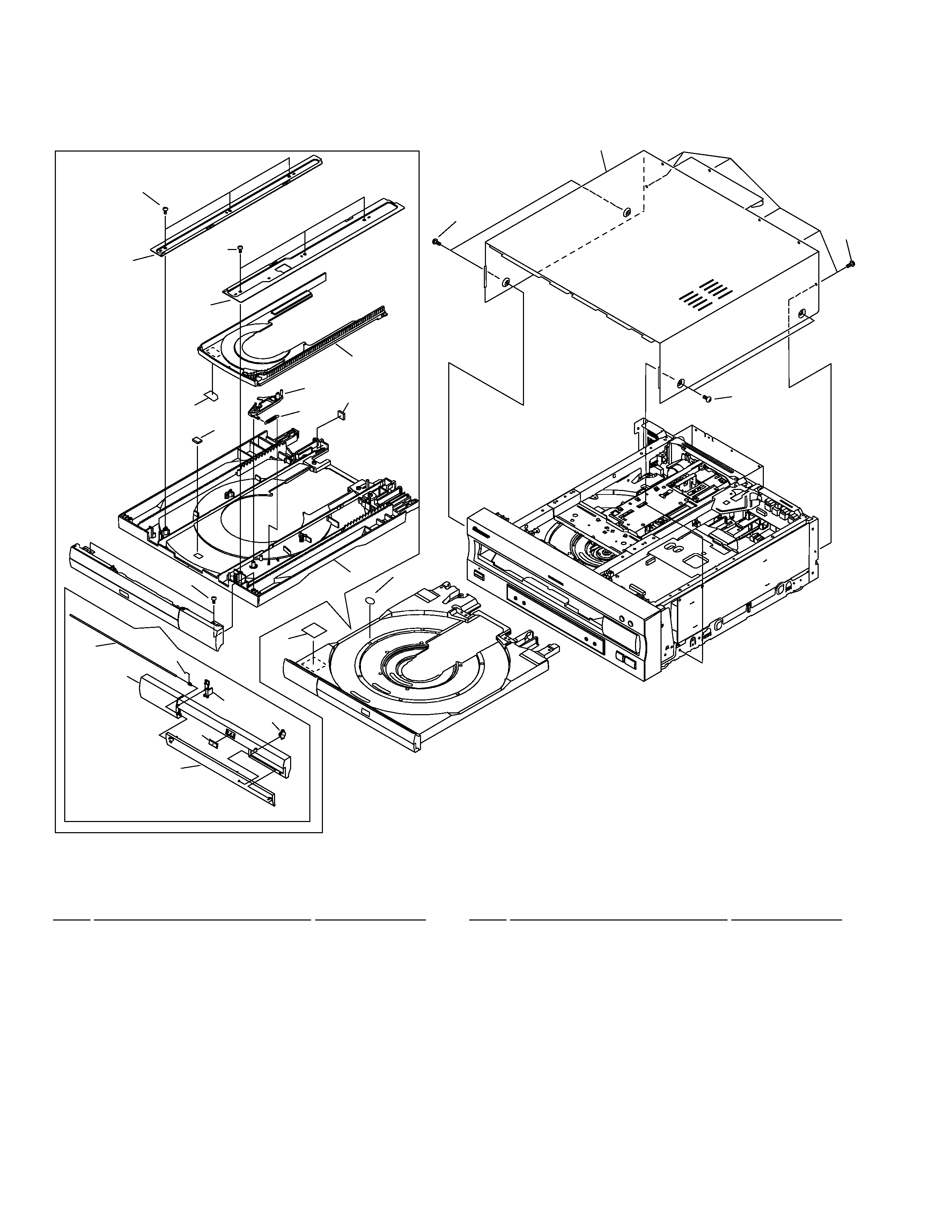
Additional Laser Caution
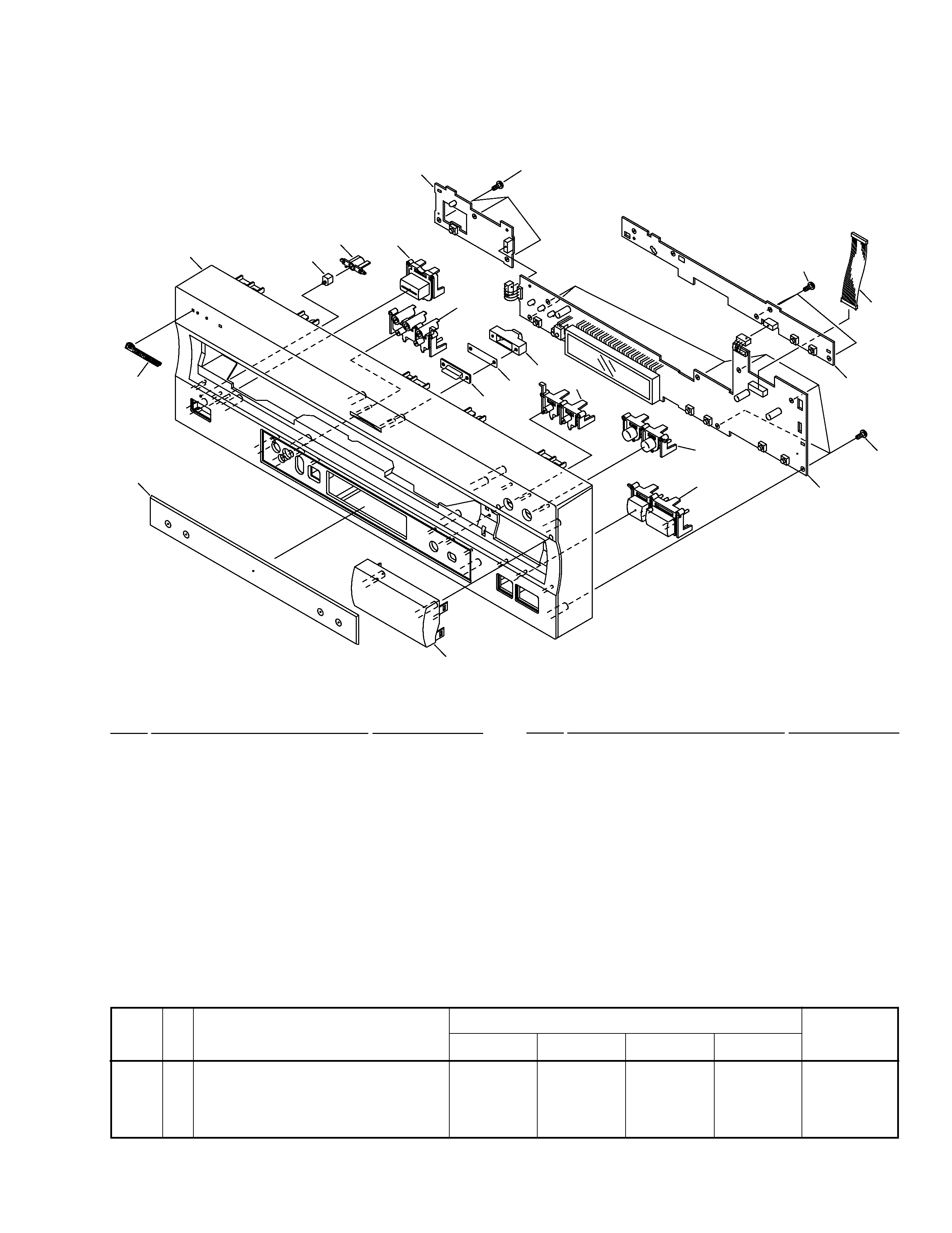
1. The ON/OFF statuses of the side-A/B detection switch
(Lever switch connecting to the TNMB assy), slider-position
detection switches (INNER and OUTER on the PKSB assy),
loading-status detection switches (SW1, 2 and 3 on the LMSB
assy), side B inside detection switch (S901 on the BISB assy)
and CLD pickup active detection switch (S903 on the LCSB
assy) are detected by the microprocessor (IC101 in the CLD
MAIN assy). Also the DVD pickup active detection switch (S902
on the DCSB assy) is detected by the microprocessor (IC501
in the DVD MAIN assy).
· To permit the laser diode of CLD pickup to oscillate, it is
required to set the CLD pickup active detection switch (S903 :
OFF) and the slider-position detection switches for the LD
ACTIVE status (INNER : OFF, OUTER: OFF), and to set the
loading-status detection switches for tilt neutral state (SW1 :
ON, SW2 : OFF, SW3 : ON). As long as these requirements
are not satisfied, the laser diode will not oscillate. When the
requirements are met in any way, the laser diode can oscillate.
The laser diode oscillation will continue if pin 13 of IC801 is
shorted to GND or the emitter and collector of Q834 are shorted
each other (fault condition) in the CLD MAIN assy.
· To permit the laser diode of DVD pickup to oscillate, it is
required to set the DVD pickup active detection switch (S902
:OFF) and each switch and a state of laser diode are contents
same as state of CLD pickup mentioned above. The laser
diode oscillation will continue if pin 13 of IC101 is shorted to
+5V (fault condition) in the DVD MAIN assy.
In the test mode
, the laser diode oscillates when the micro-
processor detects a PLAY signal, or when the PLAY key is
pressed (S104 ON in the FLKY assy), with the above require-
ments satisfied.
2. When the cover is open, close viewing through the objective
lens with the naked eye will cause exposure to a Class 1
laser beam.
: Refer to page 65.
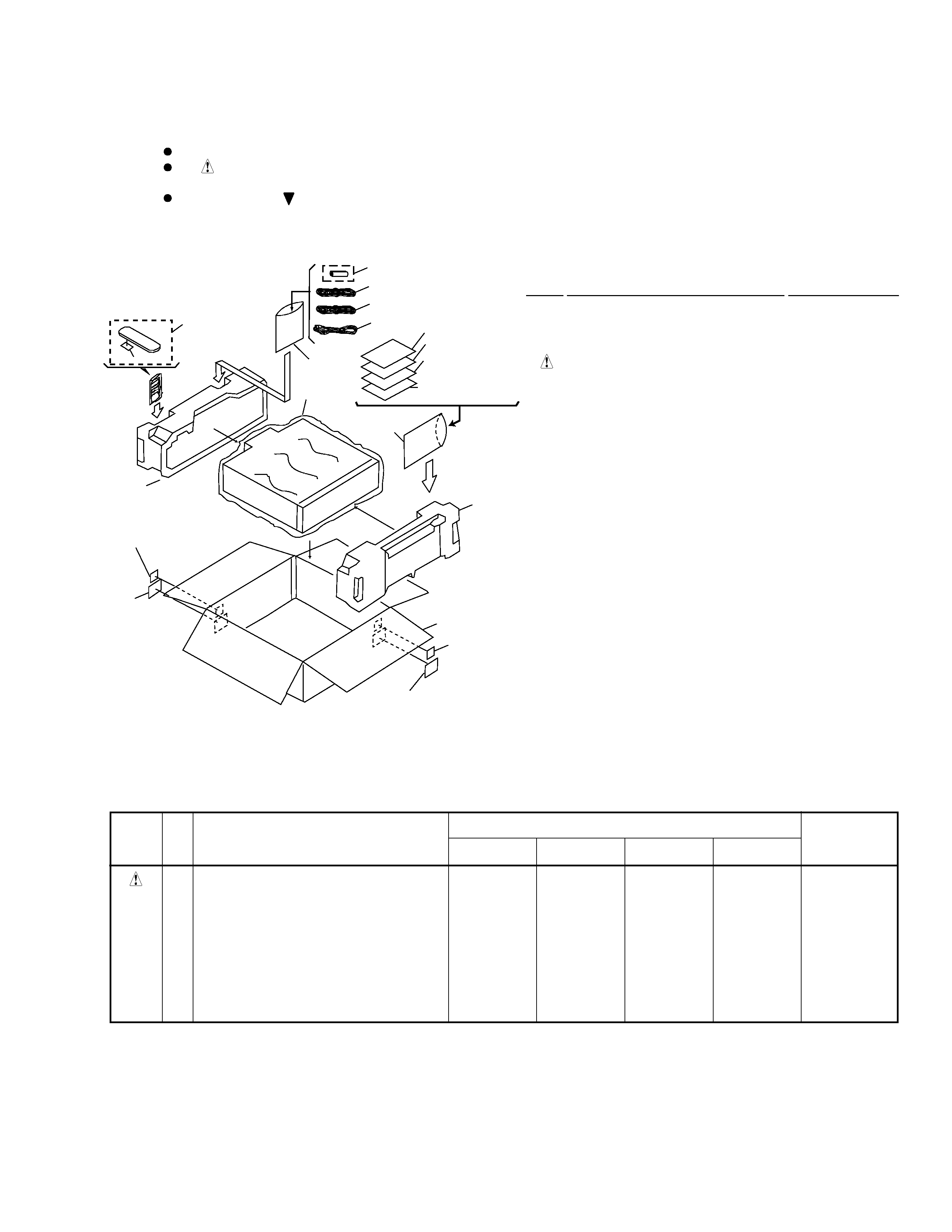
1. SAFETY INFORMATION
This service manual is intended for qualified service technicians; it is not meant for the casual
do-it-yourselfer. Qualified technicians have the necessary test equipment and tools, and have been
trained to properly and safely repair complex products such as those covered by this manual.
Improperly performed repairs can adversely affect the safety and reliability of the product and may
void the warranty. If you are not qualified to perform the repair of this product properly and safely, you
should not risk trying to do so and refer the repair to a qualified service technician.
IMPORTANT
THIS PIONNER APPARATUS CONTAINS
LASER OF CLASS 1.
SERVICING OPERATION OF THE APPARATUS
SHOULD BE DONE BY A SPECIALLY
INSTRUCTED PERSON.
LASER DIODE CHARACTERISTICS
·FOR DVD
MAXIMUM OUTPUT POWER : 7 mw
WAVELENGTH : 650 nm
·FOR CD/LD
MAXIMUM OUTPUT POWER : 5 mw
WAVELENGTH : 780-785 nm