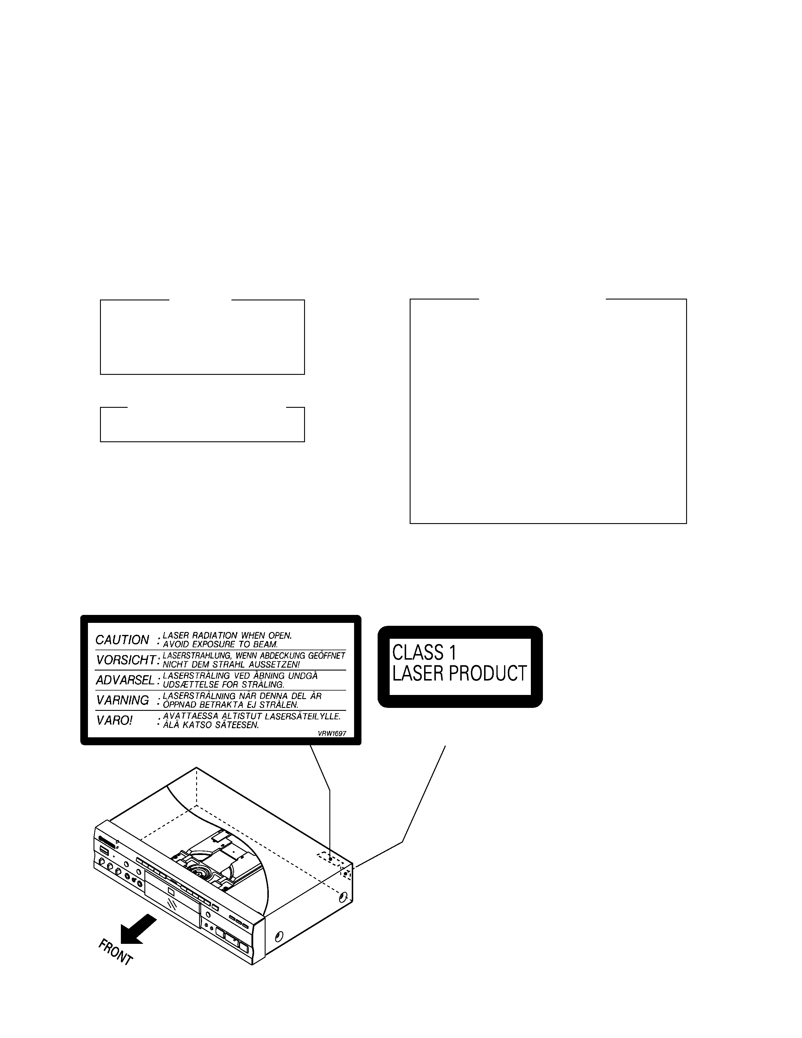
PIONEER DVK101(1) II Service Manual

Cover page of PIONEER DVK101(1) II Service Manual

Service Manual for PIONEER DVK101(1) II, downloadable as a PDF file.

Manual details

  • Immediate download after payment.
  • Delivered as a PDF file.
  • The manual has 54 pages
  • File size: 6.12 MB
  • Available language versions: English
  • Different language versions may vary sligthly in file size and page count.

We guarantee that...

  • our manuals are complete,
  • the manual includes circuit diagrams,
  • our manuals are checked with antivirus,
  • We'll issue refund if the manual is damaged, incomplete or unreadable (our refund policy)

Sample pages

Thumbnail of page 1Thumbnail of page 2Thumbnail of page 3Thumbnail of page 4
Thumbnail of page 5Thumbnail of page 6Thumbnail of page 7Thumbnail of page 8
Thumbnail of page 9
background image
ORDER NO.
PIONEER ELECTRONIC CORPORATION 4-1, Meguro 1-Chome, Meguro-ku, Tokyo 153-8654, Japan
PIONEER ELECTRONICS SERVICE, INC. P.O. Box 1760, Long Beach, CA 90801-1760, U.S.A.
PIONEER ELECTRONIC (EUROPE) N.V. Haven 1087, Keetberglaan 1, 9120 Melsele, Belgium
PIONEER ELECTRONICS ASIACENTRE PTE. LTD. 501 Orchard Road, #10-00 Wheelock Place, Singapore 238880
PIONEER ELECTRONIC CORPORATION 1998
RRV1942
DVD PLAYER
DV-K101
1. SAFETY INFORMATION ...................................... 2
2. EXPLODED VIEWS AND PARTS LIST ................ 3
3. SCHEMATIC DIAGRAM ..................................... 10
4. PCB CONNECTION DIAGRAM .......................... 23
5. PCB PARTS LIST ............................................... 33
6. ADJUSTMENT .................................................... 39
CONTENTS
7. GENERAL INFORMATION ................................ 47
7.1 IC ................................................................. 47
7.2 DISASSEMBLY ........................................... 49
7.3 BLOCK DIAGRAM ....................................... 50
8. PANEL FACILITIES AND SPECIFICATIONS .... 51
THIS MANUAL IS APPLICABLE TO THE FOLLOWING MODEL(S) AND TYPE(S).
T ­ ZZM APR. 1998 Printed in Japan
e
p
y
T
l
e
d
o
M
t
n
e
m
e
r
i
u
q
e
R
r
e
w
o
P
e
h
t
y
b
d
e
t
r
e
v
n
o
c
e
b
n
a
c
e
g
a
t
l
o
v
e
h
T
.
d
o
h
t
e
m
g
n
i
w
o
l
l
o
f
l
a
n
o
i
g
e
R
s
e
d
o
c
n
o
i
t
c
i
r
t
s
e
r
)
r
e
b
m
u
n
n
o
i
g
e
r
(
1
0
1
K
-
V
D
L
RO
V
0
4
2
-
0
2
2
/
7
2
1
-
0
1
1
C
At
c
e
l
e
s
c
i
t
a
m
o
t
u
A3
M
A
RO
V
0
4
2
-
0
2
2
/
7
2
1
-
0
1
1
C
At
c
e
l
e
s
c
i
t
a
m
o
t
u
A6
C
R
/
D
RO
V
0
4
2
-
0
2
2
/
7
2
1
-
0
1
1
C
At
c
e
l
e
s
c
i
t
a
m
o
t
u
A3
· Refer to the service guide RRV1896 for DV-505.
IC information is described in the service guide.
D DVDPLAYER DV-K101
1
2
3
4
5
6
7
8
9
0
+10
PLAYBACK ONE-TOUCH
KARAOKE
CONTROL
KARAOKE
MODE
ON/OFF
OPEN/CLOSE
STANDBY
MIN
MAX
MIN
MAX
MIN
MAX
MIC CONTROL
PREVIOUS
NEXT
RETURN
SELECT
STOP
PLAY
PAUSE
STANDBY/ ON
LOW CONTROL HIGH
KEY
ECHO
MIC 1
MIC 2
MIC 1
MIC 2
0
41
¡ ¢
78
3
Î
DIGITAL VIDEO
MC
background image
2
DV-K101
LABEL CHECK
IMPORTANT
THIS PIONNER APPARATUS CONTAINS
LASER OF CLASS 1.
SERVICING OPERATION OF THE APPARATUS
SHOULD BE DONE BY A SPECIALLY
INSTRUCTED PERSON.
LASER DIODE CHARACTERISTICS
MAXIMUM OUTPUT POWER : 7 mw
WAVELENGTH : 650 nm
Additional Laser Caution
1. Inside detection switch (S201 on the INSB assy) and loading-
status detection switch (S301 on the LOSB assy) are detected
by the microprocessor (IC501 in the DVDM assy).
· To permit the laser diode to oscillate, it is required to set the
inside detection switch for the inside position (S201 : ON) and to
set the loading-status detection switch for the clamp position (the
center terminal of S301 is shorted to +5V). The laser diode
oscillation will continue if pin 13 of IC101 is shorted to +5V (fault
condition) in the DVDM assy.
In the test mode
, the laser diode oscillates when microproces-
sor detects a PLAY signal, or when the PLAY key is pressed
(S107 ON in the FLKB assy), with the above requirements satis-
fied.
2. When the cover is open, close viewing through the objective lens
with the naked eye will cause exposure to the laser beam.
: Refer to page 41
(Printed on the Rear Panel)
1. SAFETY INFORMATION
This service manual is intended for qualified service technicians ; it is not meant for the casual do-it-
yourselfer. Qualified technicians have the necessary test equipment and tools, and have been trained
to properly and safely repair complex products such as those covered by this manual.
Improperly performed repairs can adversely affect the safety and reliability of the product and may
void the warranty. If you are not qualified to perform the repair of this product properly and safely, you
should not risk trying to do so and refer the repair to a qualified service technician.
background image
DV-K101
3
2.1 PACKING
1
Power Cord
See Contrast table (2)
2
Video Cord (L=1.5m)
VDE1048
3
Audio Cord (L=1.5m)
VDE1033
NSP
4
Dry Cell Battery (R6P, AA)
VEM-013
5
Operating Instructions
VRB1196
(English)
6
Operating Instructions
See Contrast table (2)
NSP
7
Regular User's Card
See Contrast table (2)
8
Polyethylene Bag
Z21-038
9
Remote Control Unit
VXX2576
(CU-DV020)
10
Battery Cover
VNK3703
11
Pad F
VHA1220
12
Pad R
VHA1221
13
Mirror Mat Sheet
Z23-007
14
Packing Case
See Contrast table (2)
15
RD/RC Label
See Contrast table (2)
(1) PACKING PARTS LIST
Mark No.
Description
Part No.
2. EXPLODED VIEWS AND PARTS LIST
NOTES:
· Parts marked by "NSP" are generally unavailable because they are not in our Master Spare Parts List.
· The mark found on some component parts indicates the importance of the safety factor of the part.
Therefore, when replacing, be sure to use parts of identical designation.
· Screws adjacent to mark on the product are used for disassembly.
(2) CONTRAST TABLE
RL, RAM and RD/RC types are constructed the same except for the following :
8
7
6
5
RAM and RD/RC
types only
8
10
15
9
3
14
15
4
2
1
11
12
13
RD/RC
type only
FRONT
RD/RC
type only
k
r
a
M.
o
Nn
o
i
t
p
i
r
c
s
e
D
d
n
a
l
o
b
m
y
S
.
o
N
t
r
a
P
s
k
r
a
m
e
R
L
R
e
p
y
t
M
A
R
e
p
y
t
C
R
/
D
R
e
p
y
t
P
S
N
1
6
6
7
4
1
5
1
d
r
o
C
r
e
w
o
P
)
e
s
e
n
i
h
c
-
d
a
r
T
(
s
n
o
i
t
c
u
r
t
s
n
I
g
n
i
t
a
r
e
p
O
)
e
s
e
n
i
h
c
-
p
m
i
S
(
s
n
o
i
t
c
u
r
t
s
n
I
g
n
i
t
a
r
e
p
O
d
r
a
C
s
'
r
e
s
U
r
a
l
u
g
e
R
e
s
a
C
g
n
i
k
c
a
P
l
e
b
a
L
C
R
/
D
R
4
5
1
1
G
D
A
8
6
0
1
C
R
V
d
e
s
u
t
o
N
d
e
s
u
t
o
N
1
5
7
1
G
H
V
d
e
s
u
t
o
N
7
1
0
7
G
D
A
d
e
s
u
t
o
N
9
6
0
1
C
R
V
2
1
1
1
Y
R
V
1
4
7
1
G
H
V
d
e
s
u
t
o
N
3
0
0
7
G
D
A
8
6
0
1
C
R
V
d
e
s
u
t
o
N
4
1
1
1
Y
R
V
1
5
7
1
G
H
V
0
1
7
1
W
R
V
background image
DV-K101
4
1
Bonnet Case S
VXX2581
2
DVD Plate
VAM1080
3
Tray Panel Plate
VNK4273
4
Tray Panel
VNK4158
5
Tray
VNL1731
6
Power Button Joint
See Contrast table (2)
7
Power Button
See Contrast table (2)
8
Bridge
VNE2069
9
Clamper Plate
VNE2068
10
Clamper
VNL1738
(1) EXTERIOR SECTION PARTS LIST
Mark No.
Description
Part No.
11
Tray Stopper Spring
VBH1277
12
Tray Stopper
VNL1739
13
Tray Label
VRW1628
14
Screw
BPZ26P080FZK
15
Screw
IBZ30P080FMC
16
Screw
BCZ40P060FNI
17
Screw
BBZ30P080FMC
18
Caution Label
VRW1697
Mark No.
Description
Part No.
k
r
a
M.
o
Nn
o
i
t
p
i
r
c
s
e
D
d
n
a
l
o
b
m
y
S
.
o
N
t
r
a
P
s
k
r
a
m
e
R
L
R
e
p
y
t
M
A
R
e
p
y
t
C
R
/
D
R
e
p
y
t
6
7
t
n
i
o
J
n
o
t
t
u
B
r
e
w
o
P
n
o
t
t
u
B
r
e
w
o
P
7
6
2
4
K
N
V
9
5
1
4
K
N
V
d
e
s
u
t
o
N
d
e
s
u
t
o
N
d
e
s
u
t
o
N
d
e
s
u
t
o
N
(2) CONTRAST TABLE
RL, RAM and RD/RC types are constructed the same except for the following :
16
18
1
14
9
8
10
17
16
6
7
15
2
3
4
Refer to "2.3 FRONT PANEL SECTION"
15
5
13
11
12
Refer to
"2.4 BOTTOM VIEW SECTION"
RLtype only
17
RD/RC
type only
2.2 EXTERIOR SECTION
background image
DV-K101
5
2.3 FRONT PANEL SECTION
1
FLKY Assy
See Contrast table (2)
NSP
2
PWSB Assy
See Contrast table (2)
3
KYLB Assy
VWG1961
4
Front Panel
See Contrast table (2)
5
FL Lens
VNK4272
6
Name Plate
VAM1067
7
LED Lens
PNW2019
8
Main Key
VNK4269
9
11 Key
VNK4271
10
MICB Assy
See Contrast table (2)
(1) FRONT PANEL SECTION PARTS LIST
Mark No.
Description
Part No.
11
FL Filter
VEC1643
12
Illumination Lens
VNK4264
13
Illumination Filter
VEC1983
14
Illumination Holder
VNK4265
15
Flexible Cable (14P)
VDA1646
(FLKY CN101 ­ DVDM CN105)
16
Screw
BBZ30P080FMC
NSP
17
Getter
VRW1730
18
Volume Knob
VNK4279
19
3 Key
VNK4270
20
Light Key
VNK4261
21
Earth Plate
VBK1075
22
Power Button
See Contrast table (2)
23
Lens Holder
VNK4266
Mark No.
Description
Part No.
6
4
7
23
19(1/2)
8
15
3
1
16
10
14
11
17
13
12
5
16
2
16
9
18
20
16
22
21
19(2/2)
RAM and RD/RC
types only
k
r
a
M.
o
Nn
o
i
t
p
i
r
c
s
e
D
d
n
a
l
o
b
m
y
S
.
o
N
t
r
a
P
s
k
r
a
m
e
R
L
R
e
p
y
t
M
A
R
e
p
y
t
C
R
/
D
R
e
p
y
t
P
S
N
1
2
4
0
1
2
2
y
s
s
A
Y
K
L
F
y
s
s
A
B
S
W
P
l
e
n
a
P
t
n
o
r
F
y
s
s
A
B
C
I
M
n
o
t
t
u
B
r
e
w
o
P
6
5
9
1
G
W
V
3
6
9
1
G
W
V
7
5
2
4
K
N
V
7
0
6
1
V
W
V
d
e
s
u
t
o
N
5
5
9
1
G
W
V
2
6
9
1
G
W
V
5
5
2
4
K
N
V
7
0
6
1
V
W
V
9
5
0
4
K
N
V
7
5
9
1
G
W
V
2
6
9
1
G
W
V
5
5
2
4
K
N
V
9
2
6
1
V
W
V
9
5
0
4
K
N
V
(2) CONTRAST TABLE
RL, RAM and RD/RC types are constructed the same except for the following :

Reviews

There are no reviews of this manual yet.