PIONEER DVD-U02/ZUCYV/WL Service Manual

Cover page of PIONEER DVD-U02/ZUCYV/WL Service Manual

Service Manual for PIONEER DVD-U02/ZUCYV/WL, downloadable as a PDF file.

Manual details

  • Immediate download after payment.
  • Delivered as a PDF file.
  • The manual has 33 pages
  • File size: 1.94 MB
  • Available language versions: English
  • Different language versions may vary sligthly in file size and page count.

We guarantee that...

  • our manuals are complete,
  • the manual includes circuit diagrams,
  • our manuals are checked with antivirus,
  • We'll issue refund if the manual is damaged, incomplete or unreadable (our refund policy)

Sample pages

Thumbnail of page 1Thumbnail of page 2Thumbnail of page 3Thumbnail of page 4
Thumbnail of page 5Thumbnail of page 6Thumbnail of page 7Thumbnail of page 8
Thumbnail of page 9
background image
ORDER NO.
Service
Manual
PIONEER ELECTRONIC CORPORATION
4-1, Meguro 1-Chome, Meguro-ku, Tokyo 153-8654, Japan
PIONEER ELECTRONICS SERVICE, INC. P.O. Box 1760, Long Beach, CA 90801-1760, U.S.A.
PIONEER ELECTRONIC (EUROPE) N.V . Haven 1087, Keetberglaan 1, 9120 Melsele, Belgium
PIONEER ELECTRONICS ASIACENTRE PTE. LTD. 501 Orchard Road, #10-00 Lane Crawford Place, Singapore 0923
C
C
C
C
C PIONEER ELECTRONIC CORPORATION 1998
DVD-ROM DRIVE UNIT
RRV1956
T­ZZR APR. 1998 Printed in Japan
DVD-302
CONTENTS
1. SAFETY INFORMATION .................................... 2
2. EXPLODED VIEWS AND PARTS LIST ............. 3
3. SCHEMATIC DIAGRAM ..................................... 7
4. PCB CONNECTION DIAGRAM ....................... 16
5. PCB PARTS LIST ............................................. 20
6. ADJUSTMENT .................................................. 22
7. GENERAL INFORMATION .............................. 26
7.1 IC ................................................................ 26
7.2 DISASSEMBLY .......................................... 30
7.3 BLOCK DIAGRAM ..................................... 31
8. PANEL FACILITIES AND SPECIFICATIONS
................................................................... 32
THIS MANUAL IS APPLICABLE TO THE FOLLOWING MODEL(S) AND TYPE(S).
Type
Model
DVD-302
Power Requirement
Remarks
ZUCYV/WL
DC power supplied from other system component
DVD-U02
DVD-U02
BUSY
DVD
PHONES
background image
DVD-302, DVD-U02
2
1. Laser Interlock Mechanism
The position of the switch (S601) for detecting loading
completion is detected by the system microprocessor, and
the design prevents laser diode oscillation when the
switch is not in LPS1 terminal side (when the mechanism
is not clamped and LPS1 signal is high level.) Thus, the
interlock will no longer function if the switch is deliberately
set to LPS1 terminal side. (if LPS1 signal is low level).
In the test mode* the interlock mechanism will not
function.
Laser diode oscillation will continue, if pin 19 or 20 of
µPC2510 (IC50) on the MAIN board assy connected to
high level, or else the terminais of Q50 or Q51 are shorted
to each other .
2. When the cover is opened, close viewing of the objective
lens with the naked eye will cause exposure to a Class 1
laser beam.
1. SAFETY INFORMATION
IMPORTANT
THIS PIONEER APPARATUS CONTAINS
LASER OF CLASS 1.
SERVICING OPERATION OF THE APPARATUS
SHOULD BE DONE BY A SPECIALLY
INSTRUCTED PERSON.
LASER DIODE CHARACTERISTICS
MAXIMUM OUTPUT POWER: 7 mw
WAVELENGTH: 640 nm(DVD) , 780 nm(CD-ROM)
This service manual is intended for qualified service technicians; it is not meant for the casual
do-it-yourselfer. Qualified technicians have the necessary test equipment and tools, and have been
trained to properly and safely repair complex products such as those covered by this manual.
Improperly performed repairs can adversely affect the safety and reliability of the product and may
void the warranty. If you are not qualified to perform the repair of this product properly and safely, you
should not risk trying to do so and refer the repair to a qualified service technician.
WARNING
Lead in solder used in this product is listed by the California Health and Welfare agency as a known reproductive toxicant whic h
may cause birth defects or other reproductive harm (California Health & Safety Code, Section 25249.5).
When servicing or handling circuit boards and other components which contain lead in solder, avoid unprotected skin contact with
the solder. Also, when soldering do not inhale any smoke or fumes produced.
Additional Laser Caution
* Refer to page 23.
This product complies with the EMC Directives (89/336/EEC,
92/31/EEC) and CE Marking Directive (93/68/EEC).
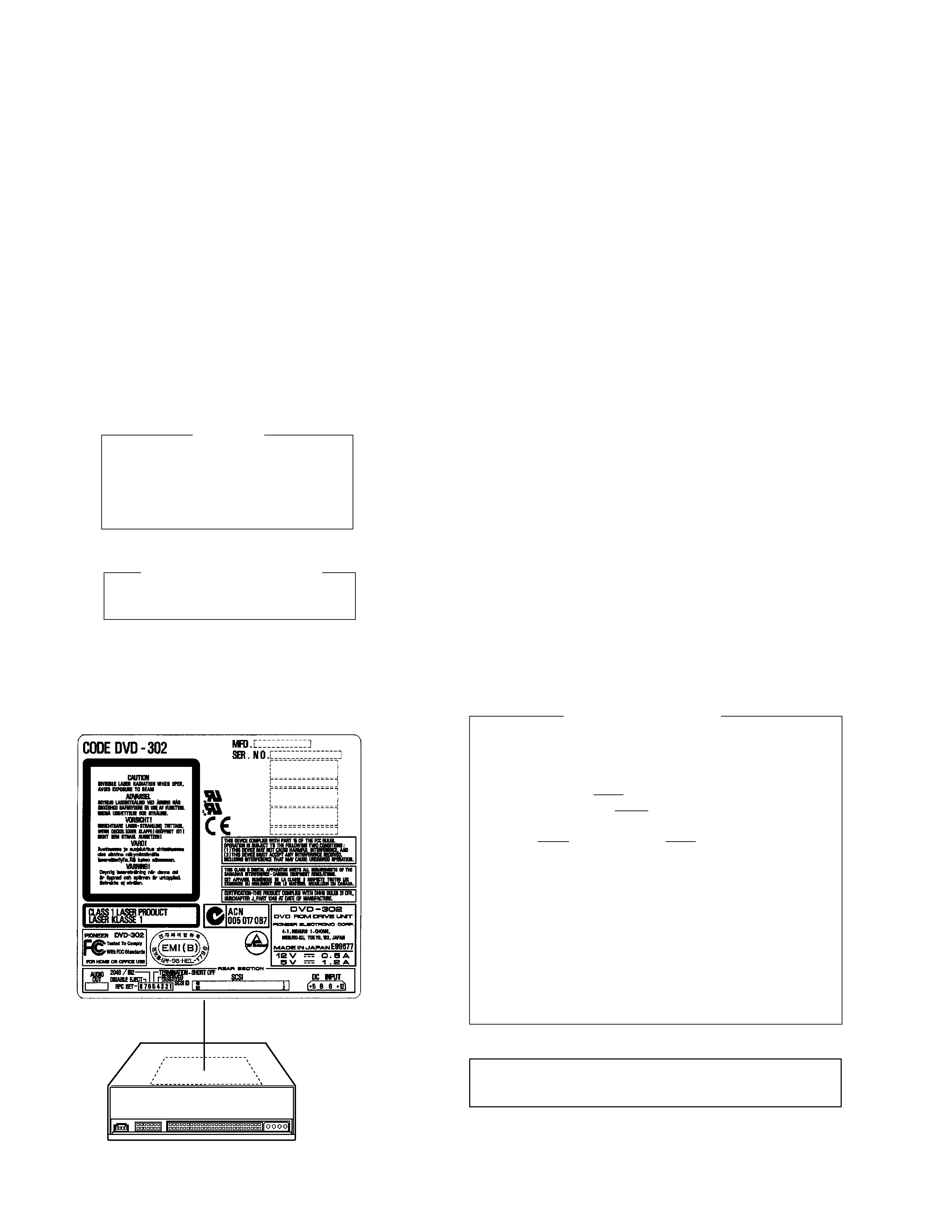
LABEL CHECK
Rear View
DRW1885
background image
DVD-302, DVD-U02
3
Front
3
2
3
1
4
10
12
9
8
7
5
13
11
6
4
5 Drives
1
2
1
3
Top
Front
5
1
4
6
7
8
Packing for DVD-U02
2. EXPLODED VIEWS AND PARTS LIST
2.1 PACKING
¶ Parts List for DVD-302
Mark No.
Description
Part No.
Mark No.
Description
Part No.
Packing for DVD-302
NOTES :
÷ Parts marked by " NSP " are generally unavailable because they are not in our Master Spare Parts List.
÷ The
mark found on some component parts indicates the importance of the safety factor of the part.
Therefore, when replacing, be sure to use parts of identical designation.
÷ Screw adjacent to
mark on the product are used for disassembly.
1
Pad (Bulk)
DHA1402
2
Packing Case
DHG1826
NSP
3
Polyethylene Bag (235X320)
Z21-018
4
Operating Instructions
DRC1082
(English/ French/ German )
5
Plate
DHC1048
6
Pin for emergency ejection
DEX1007
7
CAUTION Tag
DRW1897
NSP
8
Polyethylene Bag (75X120)
Z21-006
¶ Parts List for DVD-U02
1
Pad
DHA1414
2
Master Carton
DHG1827
3
Packing Case
DHG1828
NSP
4
Polyethylene Bag (235X320)
Z21-019
5
Operating Instructions
DRC1083
(English/ French/ German/
Italian/ Japanese)
6
Audio Cable (L=0.6m)
DKP3369
7
Polyethylene Bag(70X100)
DHL1089
8
Mounting screw
AMZ30P060FMC
9
Short-circuit socket
DKX1042
10
Installation instructions
DRB1226
11
Software device drive disk(SCSI) DWX1809
12
Pin for emergency ejection
DEX1007
13
CAUTION Tag
DRW1897
background image
DVD-302, DVD-U02
4
2.2 EXTERIOR SECTION
1
MAIN BOARD ASSY
DWX1855
2
CONNECTOR ASSY 3P
DKP3377
NSP
3
FRONT VESSEL ASSY
DAH1861
(For DVD-302)
NSP
3
FRONT VESSEL ASSY
DAH1864
(For DVD-U02)
NSP
4
TOP CASE
DNC1470
5
SLOT IN MECHA ASSY-S
DXX2410
NSP
6
LABEL
DRW1885
7
LENS
DAC1855
NSP
8
BOTTOM CASE
DNC1477
9
FRONT VESSEL ASSY-S
DEA1010
(For DVD-302)
9
FRONT VESSEL ASSY-S
DEA1016
(For DVD-U02)
10
CONTROL BUTTON
DAC1884
NSP
11
FRONT SHEET
DED1130
12
..............
13
SCREW
BBZ26P080FMC
14
SHORT SOCKET
DKX1042
NSP
15
SILICON SEAT
DEB1380
16
SCREW
BPZ20P100FMC
17
SPACER
DEB1392
Mark No.
Description
Part No.
Mark No.
Description
Part No.
A
1
2
3
4
5
7
9
10
11
13
13
14
6
8
17
16
15
Refer to " 2.3 SLOT-IN MECHANISM ASSY SECTION".
TO 2.3 SLOT-IN MECHANISM ASSY SECTION
¶ EXTERIOR SECTION PARTS LIST
background image
DVD-302, DVD-U02
5
2.3 SLOT IN MECHANISM ASSY SECTION
Mark No.
Description
Part No.
1
CLAMPER ASSY
DXA1821
2
CLAMP SPRING
DBH1374
3
GUIDE SPRING
DBH1375
NSP
4
LEVER ( 1 )
DNK3402
5
SL MECHA BOARD ASSY
DWX1796
6
MAIN CAM
DNK3407
7
LOADING GEAR
DNK3409
NSP
8
WORM GEAR
DNK3410
9
FLOATING RUBBER
DEB1379
10
EARTH SPRING
DBH1398
11
CLAMP ARM
DNK3404
12
DRIVE GEAR
DNK3565
13
CHASSIS D
DNK3479
14
DISK GUIDE
DNK3478
15
.............
16
EJECT LEVER
DNK3548
17
LOADING LEVER
DNK3406
18
SCREW
ABZ26P050FMC
19
FLOAT FASTENER
DBA1110
NSP
20
LOADING BASE
DNK3494
21
SERVO MECHANISM ASSY-S
DXX2413
22
MOTOR LEAD WIRER (Red)
DDB1078
23
MOTOR LEAD WIRER (Black)
DDB1079
NSP
24
LEVER (2)
DNK3504
NSP
25
LOADING MOTOR
DXM1093
26
POLYSYEN WASHER
DEC2213
27
SPACER
DEB1387
19
26
9
13
21
19
22
5
25
8
23
20(1/3)
16
20(2/3)
20(3/3)
6
12
7
17
1
2
11
4
24
3
14
9
26
19
9
26
Refer to " 2.4 SERVO
MECHANISM ASSY SECTION".
From " 2.2 EXTERIOR SECTION".
27
10
18
A
¶ SLOT IN MECHANISM ASSY SECTION
PARTS LIST

Reviews

There are no reviews of this manual yet.