PIONEER DV-C505 Service Manual

Cover page of PIONEER DV-C505 Service Manual

Service Manual for PIONEER DV-C505, downloadable as a PDF file.

Manual details

  • Immediate download after payment.
  • Delivered as a PDF file.
  • The manual has 102 pages
  • File size: 9.6 MB
  • Available language versions: English
  • Different language versions may vary sligthly in file size and page count.

We guarantee that...

  • our manuals are complete,
  • the manual includes circuit diagrams,
  • our manuals are checked with antivirus,
  • We'll issue refund if the manual is damaged, incomplete or unreadable (our refund policy)

Sample pages

Thumbnail of page 1Thumbnail of page 2Thumbnail of page 3Thumbnail of page 4
Thumbnail of page 5Thumbnail of page 6Thumbnail of page 7Thumbnail of page 8
Thumbnail of page 9
background image
ORDER NO.
PIONEER CORPORATION 4-1, Meguro 1-chome, Meguro-ku, Tokyo 153-8654, Japan
PIONEER ELECTRONICS (USA) INC. P.O. Box 1760, Long Beach, CA 90801-1760, U.S.A.
PIONEER EUROPE NV Haven 1087, Keetberglaan 1, 9120 Melsele, Belgium
PIONEER ELECTRONICS ASIACENTRE PTE. LTD. 253 Alexandra Road, #04-01, Singapore 159936
PIONEER CORPORATION 2002
Î
DV-C505
RRV2619
DVD PLAYER
DV-C505
THIS MANUAL IS APPLICABLE TO THE FOLLOWING MODEL(S) AND TYPE(S).
Model
Type
Power Requirement
Reginal restriction
codes (Region No.)
Remarks
DV-C505
KUXU
AC120V
1
DV-C505
KCXU
AC120V
1
For details, refer to "Important symbols for good services" .
T-ZZR JULY 2002 printed in Japan
background image
DV-C505
2
1234
123
4
C
D
F
A
B
E
SAFTY INFORMATION
This service manual is intended for qualified service technicians; it is not meant for the casual
do-it-yourselfer. Qualified technicians have the necessary test equipment and tools, and have been
trained to properly and safely repair complex products such as those covered by this manual.
Improperly performed repairs can adversely affect the safety and reliability of the product and may
void the warranty. If you are not qualified to perform the repair of this product properly and safely, you
should not risk trying to do so and refer the repair to a qualified service technician.
WARNING
This product contains lead in solder and cer tain electrical par ts contain chemicals which are known to the state of California to
cause cancer, bir th defects or other reproductive harm.
Health & Safety Code Section 25249.6 ­ Proposition 65
NOTICE
(FOR CANADIAN MODEL ONLY)
Fuse symbols
(fast operating fuse)
and/or
(slow operating fuse) on PCB indicate that replacement
parts must be of identical designation.
REMARQUE
(POUR MODÈLE CANADIEN SEULEMENT)
Les symboles de fusible
(fusible de type rapide)
et/ou
(fusible de type lent) sur CCI indiquent que
les pièces de remplacement doivent avoir la même désignation.
ANY MEASUREMENTS NOT WITHIN THE
LIMITS OUTLINED ABOVE ARE INDICATIVE
OF A POTENTIAL SHOCK HAZARD AND
MUST BE CORRECTED BEFORE RETURN-
ING THE APPLIANCE TO THE CUSTOMER.
2. PRODUCT SAFETY NOTICE
Many electrical and mechanical parts in the appliance
have special safety related character istics. These are
often not evident
from visual
inspection nor the
protection afforded by them necessarily can be obtained
by using replacement components rated for voltage,
wattage, etc. Replacement par ts which have these
special safety character istics are identified in this
Service Manual.
Electr ical components having such features are
identified by marking with a
on the schematics and
on the parts list in this Service Manual.
The use of a substitute replacement component which
does not have the same safety characteristics as the
PIONEER recommended replacement one, shown in the
parts list in this Service Manual, may create shock, fire,
or other hazards.
Product Safety is continuously under review and new
instructions are issued from time to time. For the latest
infor mation, always consult the current PIONEER
Service Manual. A subscription to, or
additional copies
of, PIONEER Ser vice Manual may be obtained at a
nominal charge from PIONEER.
(FOR USA MODEL ONLY)
1. SAFETY PRECAUTIONS
The following check should be perfor med for the
continued protection of the customer and ser vice
technician.
LEAKAGE CURRENT CHECK
Measure leakage current to a known ear th ground
(water pipe, conduit, etc.) by connecting a leakage
current tester such as Simpson Model 229-2 or
equivalent between the ear th ground and all exposed
metal par ts of the appliance (input/output ter minals,
screwheads, metal overlays, control shaft, etc.). Plug
the AC line cord of the appliance directly into a 120V
AC 60 Hz outlet and turn the AC power switch on. Any
current measured must not exceed 0.5 mA.
Device
under
test
Leakage
current
tester
Earth
ground
Reading should
not be above
0.5 mA
Also test with
plug reversed
(Using AC adapter
plug as required)
Test all
exposed metal
surfaces
AC Leakage Test
background image
DV-C505
3
5
678
56
7
8
C
D
F
A
B
E
[ Important symbols for good services ]
In this manual, the symbols shown-below indicate that adjustments, settings or cleaning should be made securely.
When you find the procedures bearing any of the symbols, be sure to fulfill them:
2. Adjustments
To keep the original performances of the product, optimum adjustments or specification confirmation is indispensable.
In accordance with the procedures or instructions described in this manual, adjustments should be performed.
3. Cleaning
For optical pickups, tape-deck heads, lenses and mirrors used in projection monitors, and other parts requiring cleaning,
proper cleaning should be performed to restore their performances.
5. Lubricants, glues, and replacement parts
Appropriately applying grease or glue can maintain the product performances. But improper lubrication or applying
glue may lead to failures or troubles in the product. By following the instructions in this manual, be sure to apply the
prescribed grease or glue to proper portions by the appropriate amount.For replacement parts or tools, the prescribed
ones should be used.
4. Shipping mode and shipping screws
To protect the product from damages or failures that may be caused during transit, the shipping mode should be set or
the shipping screws should be installed before shipping out in accordance with this manual, if necessary.
1. Product safety
You should conform to the regulations governing the product (safety, radio and noise, and other regulations), and
should keep the safety during servicing by following the safety instructions described in this manual.
Discs compatible with this
player
Any disc that displays one of the following
logos should play in this player. Other
formats, including DVD-Audio, DVD-RAM,
DVD-ROM, CD-ROM (except those that
contain MP3 files), SACD and Photo CD will
not play.
Audio-CD
DVD-Video
Video-CD
CD-R
CD-RW
background image
DV-C505
4
1234
123
4
C
D
F
A
B
E
CONTENTS
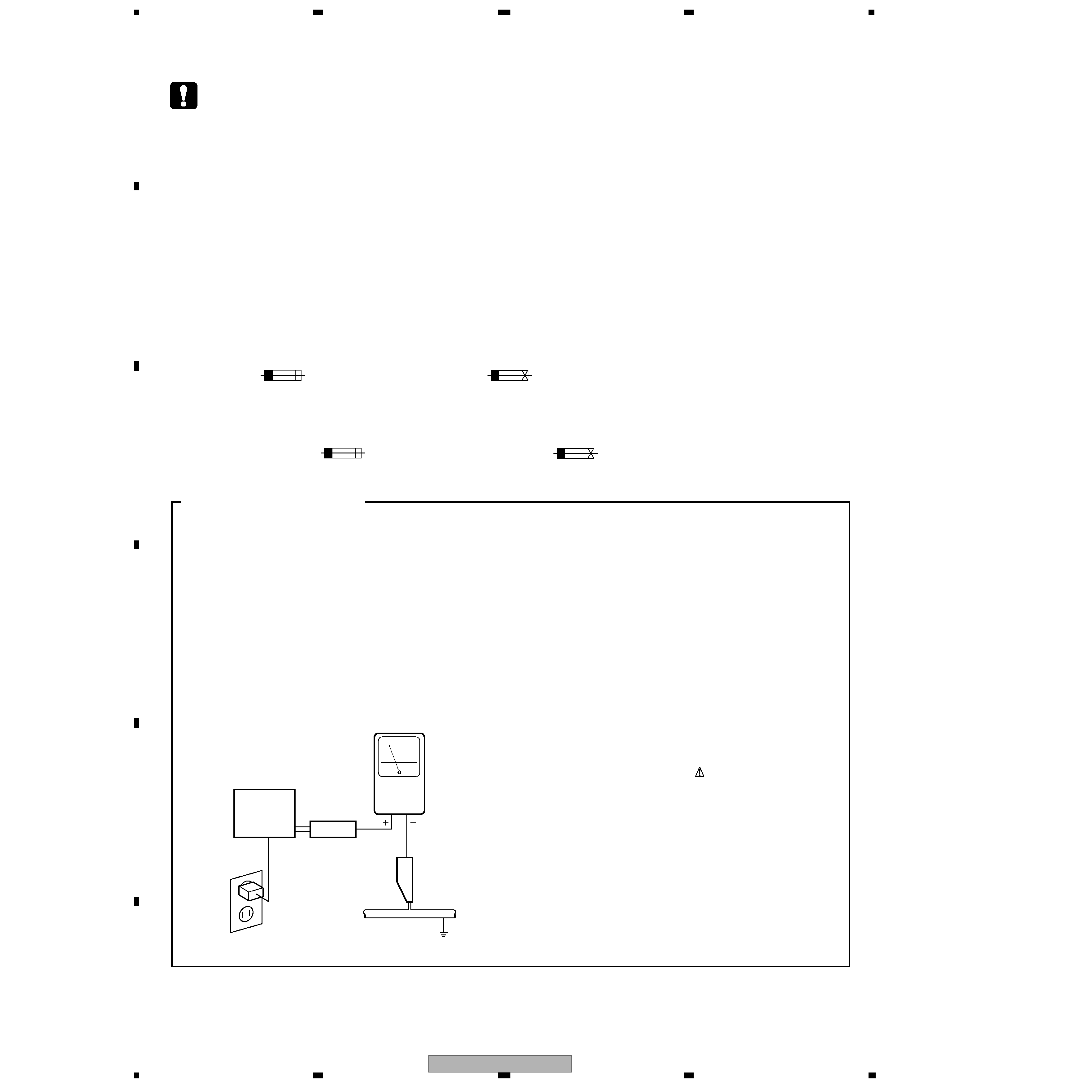
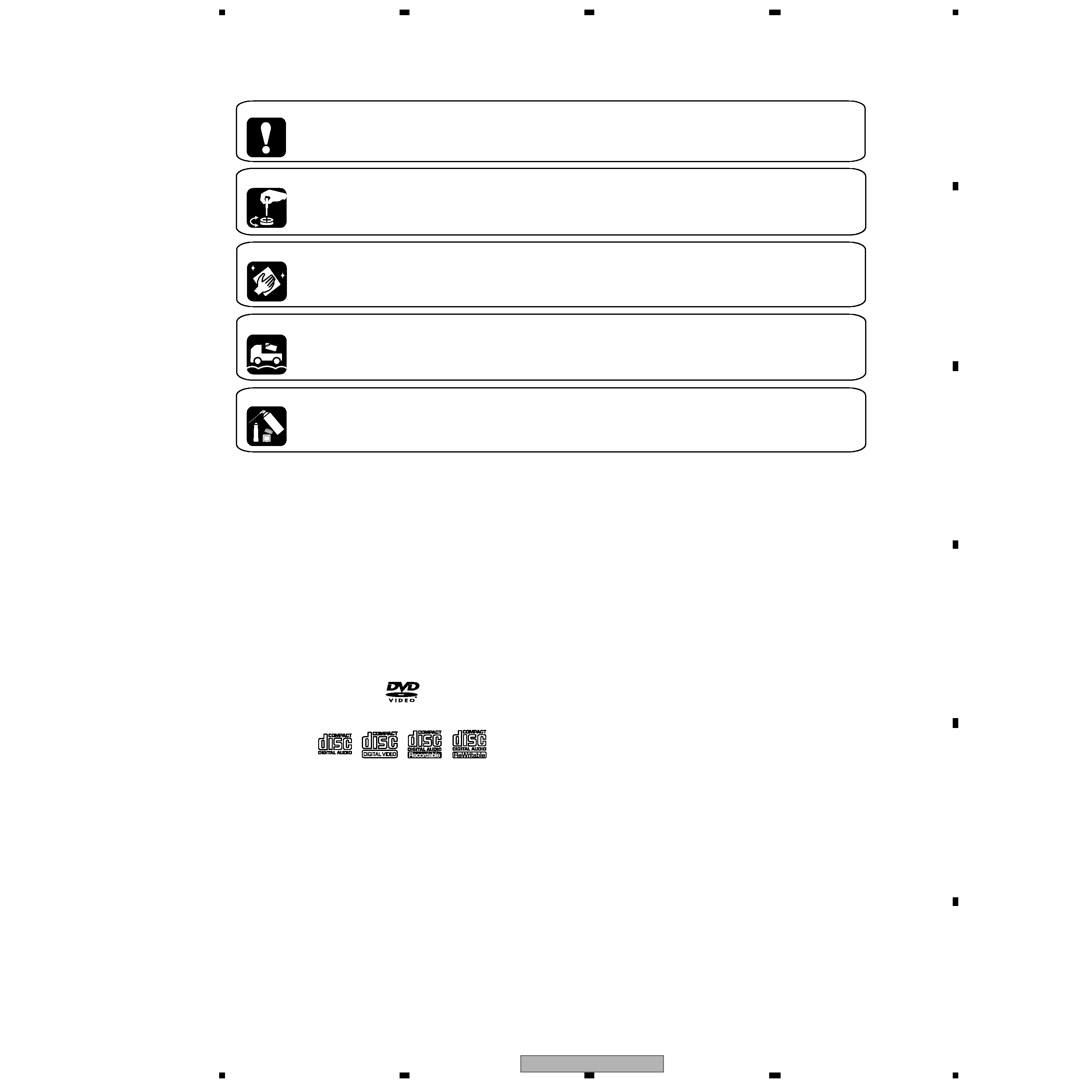
SAFTY INFORMATION ....................................................................................................................................... 2
1. SPECIFICATIONS ............................................................................................................................................ 5
2. EXPLODED VIEWS AND PARTS LIST ............................................................................................................ 6
2.1 PACKING ................................................................................................................................................... 6
2.2 EXTERIOR SECTION................................................................................................................................ 8
2.3 TABLE MECHANISM SECTION .............................................................................................................. 10
2.4 TRAVERSE MECHANISM ASSY-S ......................................................................................................... 12
3. BLOCK DIAGRAM AND SCHEMATIC DIAGRAM ..........................................................................................14
3.1 BLOCK DIAGRAM ................................................................................................................................... 14
3.2 OVERALL WIRING DIAGRAM................................................................................................................. 18
3.3 FJMB ASSY(1/5)...................................................................................................................................... 20
3.4 FJMB ASSY(2/5)...................................................................................................................................... 22
3.5 FJMB ASSY(3/5)...................................................................................................................................... 24
3.6 FJMB ASSY(4/5)...................................................................................................................................... 26
3.7 FJMB ASSY(5/5)...................................................................................................................................... 28
3.8 FLKY, DSSB and PWSB ASSYS ............................................................................................................. 30
3.9 POWER SUPPLY UNIT............................................................................................................................ 32
4. PCB CONNECTION DIAGRAM ..................................................................................................................... 33
4.1 TRSB, SSRB, LOMB and SSIB ASSYS................................................................................................... 33
4.2 FJMB ASSY ............................................................................................................................................. 34
4.3 FLKY, DSSB and PWSB ASSYS ............................................................................................................. 38
4.4 POWER SUPPLY UNIT............................................................................................................................ 40
5. PCB PARTS LIST ........................................................................................................................................... 41
6. ADJUSTMENT ............................................................................................................................................... 44
6.1 ADJUSTMENT ITEMS and LOCATION ................................................................................................... 44
6.2 JIGS and MEASURING INSTRUMENTS ................................................................................................ 44
6.3 NECESSARY ADJUSTMENT POINTS ................................................................................................... 45
6.4 TEST MODE ............................................................................................................................................ 46
6.5 MECHANISM ADJUSTMENT .................................................................................................................. 47
7. GENERAL INFORMATION ............................................................................................................................. 50
7.1 DIAGNOSIS ............................................................................................................................................. 50
7.1.1 TEST MODE ......................................................................................................................................... 50
7.1.2 DISPLAY OF THE MECHANISM ERROR HISTORY............................................................................ 56
7.1.3 TEST POINT LOCATION ...................................................................................................................... 60
7.1.4 TROUBLE SHOOTING ......................................................................................................................... 64
7.1.5 SEQUENCE AFTER THE POWER ON ................................................................................................ 66
7.1.6 DISASSEMBLY ..................................................................................................................................... 67
7.1.7 TROUBLE SHOOTING FOR MECHANISM SECTION......................................................................... 77
7.2 PARTS...................................................................................................................................................... 79
7.2.1 IC .......................................................................................................................................................... 79
7.2.2 DISPLAY ............................................................................................................................................... 96
7.3 CLEANING............................................................................................................................................... 97
8. PANEL FACILITIES ........................................................................................................................................ 98
background image
DV-C505
5
5
678
56
7
8
C
D
F
A
B
E
1. SPECIFICATIONS
General
System ........................................... DVD player
Power requirements ............... AC 120 V
, 60 Hz
Power consumption ................................. 13 W
Power consumption (standby) ......................0.3 W
Weight .....................................4.5 kg (9lb 15oz)
Dimensions ..... 420 (W) x 100 (H) x 374 (D) mm
(16 9/16 (W) x 315/16 (H) x 1412/16 (D) in.)
Operating temperature ..............+5
°C to +35°C
(+41
°F to +96°F)
Operating humidity .......................... 5% to 85%
(no condensation)
S-Video output
Y (luminance) - Output level ........ 1 Vp-p (75
)
C (color) - Output level ......... 286 mVp-p (75
)
Jack ..................................................... S-Video
Video output
Output level ................................ 1 Vp-p (75
)
Jack ..........................................................RCA
Component V ideo output (Y , PB, PR)
Output level .......................... Y: 1.0 Vp-p (75 )
PB, PR: 0.7 Vp-p (75
)
Jacks ....................................................... RCA
Audio output (2 stereo pair)
Output level ....................... During audio output
200 mVrms (1 kHz, ­20 dB)
Number of channels .......................................... 2
Jacks .............................................................RCA
Digital audio characteristics
Frequency response..................... 4 Hz to 44 kHz
(DVD fs: 96 kHz)
S/N ratio .................................................... 118 dB
Dynamic range ......................................... 101 dB
Total harmonic distortion .....................
0.0016 %
Wow and flutter ..............
Limit of measurement
(
± 0.001% W.. PEAK) or lower
Digital output
Optical digital output ...................... EIAJ Optical
Coaxial digital output ................................... RCA
Accessories
Stereo audio cable............................................. 1
Video cable ......................................................... 1
Power cable ........................................................ 1
Remote control ................................................... 1
AA/R6P dry cell batteries .................................. 2
Operating Instructions ...................................... 1
Warranty card ..................................................... 1
· The specifications and design of this
product are subject to change without
notice, due to improvement.
· Manufactured under license from Dolby
Laboratories. "Dolby" and the double-D
symbol are trademarks of Dolby Laboratories.
· "DTS" is a registered trademark of Digital
Theater Systems, Inc.
· TruSurround and the
® symbol are
trademarks of SRS Labs, Inc. TruSurround
technology is incorporated under license from
SRS Labs, Inc.
Video Cable (L=1.5m): VDE1055
Audio Cable (L=1.5m): VDE1054
AA/R6P Dry Cell Batteries
Power Cable : ADG7022
Remote Control : VXX2811
Accessories
White
Red
Yellow
0
1
23
4
56
78
9
CLEAR
ENTER
ANGLE
AUDIO
TOP MENU
SETUP
SUBTITLE
PLAY MODE SURROUND
ZOOM
DISPLAY
MENU
RETURN
ENTER
STANDBY/ON
OPEN/CLOSE
4
/
e
E/
13
¡
¢
8
7
0

Reviews

There are no reviews of this manual yet.